Publication No. 5105703
32
5. Fault Finding Guide
Fault Finding
Star
t
All ser
vice on
Ensure system
change-o
v
e
r
s
witch in control
bo
x is set
correctly
Call f
or heat
Ensure there is
240 10%
betw
een L & N
and 240v 10%
betw
een Swl
and N.
Has o
v
erheat
ther
mostat
oper
ated?
Chec
k fuse on,
electronic
control
Chec
k all
appliances
wir
ing and
electr
ical
components
.
Chec
k full oper
ational
sequence to ensure
that the boiler and
pump o
v
err
un
ther
mostat
are oper
ating correctly
Fully pumped
system.
Chec
k pump is
oper
ating and
w
ater is
circulating
correctly
.
Gr
a
vity DHW
system ensure
o
v
erheat
ther
mostat
b
ulb is located
correctly
see Fig.
21.
Press o
v
erheat
reset b
utton.
+_
+_
+_
Is there 240v
10% betw
een
T6 &
T2 on
electronic control?
Chec
k and/or
replace air
pressure s
witch
Replace
appropr
iate
ther
mostat.
See note
Replace
o
v
erheat
ther
mostat
Replace
pump
o
v
err
un
ther
mostat
Boiler
oper
ating
satisf
actor
y
Flame Super
vision
T
esting
With the boiler r
unning, tur
n off at the boiler ther
mostat.
T
empor
ar
ily restr
ict the pilot gas supply b
y
fully scre
wing in the
gas v
alv
e pilot scre
w cloc
kwise
. T
u
rn
on at the boiler ther
mostat:
a spar
k will be present, indicating GV2 is electr
ically disconnected,
and the boiler will not light.
No
w reinstate the pilot supply (three
complete anti-cloc
kwise tur
ns);
pilot and main boiler will light in the
nor
mal manner
.
T
est Pr
ocedure For Measuring Flame Current
Disconnect the white wire from GV2 on gas control v
alv
e and
connect it via a suitab
le test s
witch to neutr
al as sho
wn.
Set
test s
witch to OFF
. Inser
t an appro
v
ed ammeter in ser
ies
with the spar
k electrode
.
T
u
rn
ON the electr
icity supply and restar
t the boiler
.
NO
TE:
The pilot will light b
ut not the main b
u
rner as GV2 is
disconnected.
When the pilot is estab
lished set the test s
witch to ON.
This
will stop the spar
k and allo
w a steady flame current to be
measured.
NO
TE:
When pumped centr
al heating is
in oper
ation the boiler is controlled b
y
the
main boiler ther
mostat.
When only a g
ra
vity hot w
ater circuit is in
oper
ation the boiler is controlled b
y
the
main boiler ther
mostat when set at No
.4
or belo
w
. At setting abo
v
e
No
.4 the
temper
ature is limited b
y
the oper
ation
of the g
ra
vity control ther
mostat.
Are all
v
alv
es
open and
w
ater
circulating
correctly
T
est
Switch
White wire
disconnected
from GV2
N
F
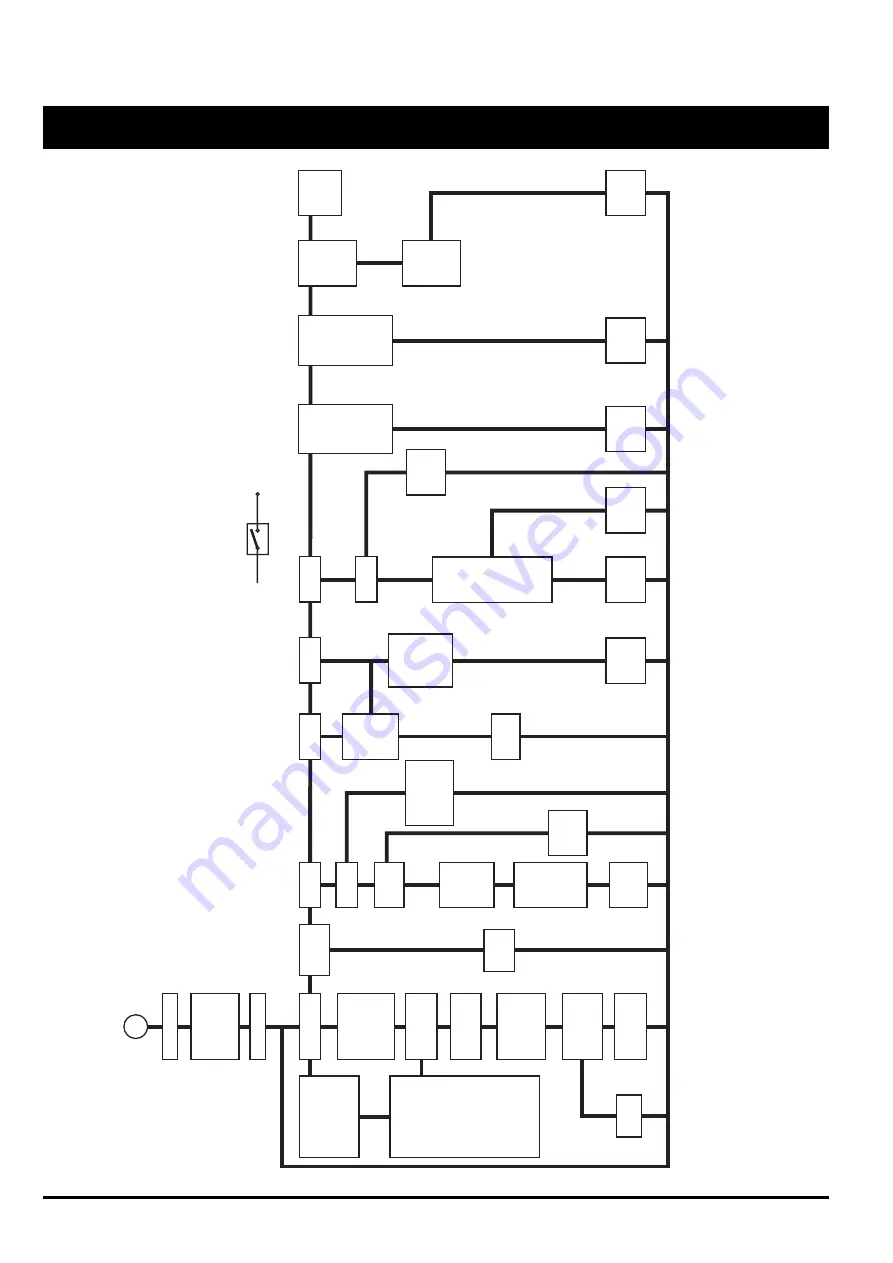
ault Finding Char
t
Chec
k that
pilot is not
par
tially
b
loc
k
ed.
Chec
k
solenoid
GV1 replace
if necessar
y
Replace
electronic
control
Does main
b
u
rner light?
Does spar
k
stop?
Switch off
e
xter
nal
electr
icity
supply and
follo
w the
test
procedure
descr
ibed
abo
v
e
.
Is there
more than
1.5µA
recorded?
If gas is not
flo
wing out
of pilot, chec
k
jet is not
b
loc
k
ed & pilot
scre
w on gas
v
alv
e open
Chec
k
solenoid
GV2 replace
if necessar
y
Does boiler
cycle off and
on under
control of
the boiler
ther
mostat
when system
is up to
temper
ature
.
See note
F
ollo
wing a
run per
iod at
maxim
um
temper
ature
,
does pump
contin
ue to
oper
ate after
boiler
ther
mostat
oper
ates?
Boiler
oper
ate
without
tr
ipping the
o
v
erheat
ther
mostat?
Fully pumped
system only
Does Pilot
light?
Replace
electronic
control
Chec
k case door
seal and replace
if damaged.
Fully
tighten tw
o lo
w
e
r
secur
ing scre
ws
.
Is electrode
spar
king?
Is case door
leaking?
Are spar
ks
occurr
ing
else
where?
Is there
240v 10%
betw
een T2
and T4
on electrode
control
Ensure air
pressure
tubes are
not kink
ed
or b
loc
k
e
d
and are
correctly
fitted.
Chec
k and/
or replace
air pressure
s
witch
Chec
k and/
or replace
electrode
lead
Does f
a
n
oper
ate?
Does f
an r
u
n
without
cycling on/off
Replace
electronic
control
PRF0034A
Replace
fa
n
Does Pilot
remain lit?
Ye
s
Y
e
s
Ye
s
Ye
s
Ye
s
Y
e
s
Ye
s
Y
e
s
Ye
s
Ye
s
Ye
s
Y
e
s
Ye
s
Ye
s
Ye
s
Ye
s
Ye
s
No
No
No
No
No
No
No
No
No
No
No
No
No
No
No
No
No
+_
Is there
240v 10%
betw
een
T2 &
T3 on
electronic
control?
+_
Fig. 31


