Installation Requirements - Page 11
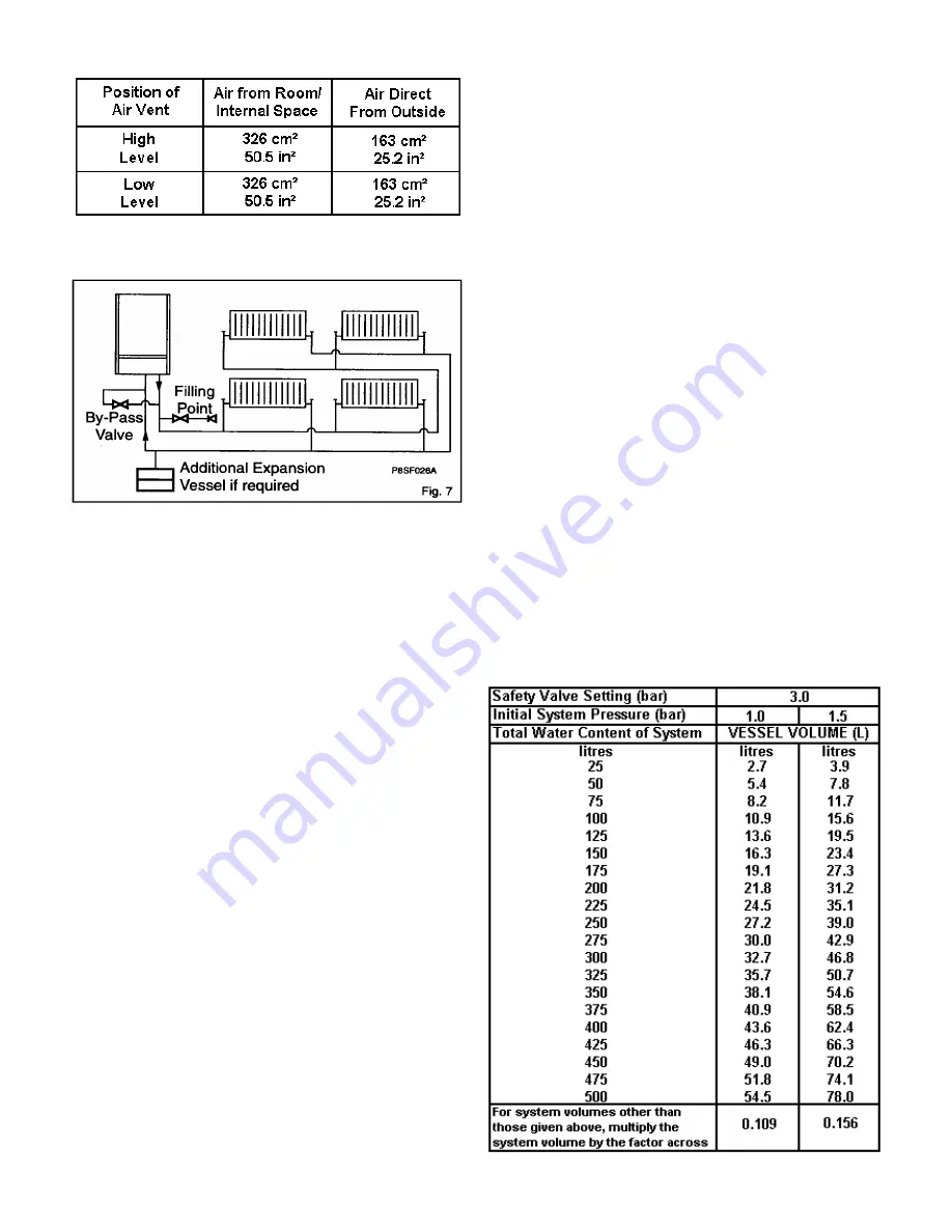
Table 2. Air Supply
1.5
Guide to System Requirements
(Figs. 7 & 9)
These combination boilers are specifically designed for
sealed systems
only. Therefore the central heating system
should be in accordance with the relevant recommendations
given in BS 6798 and also, smallbore and microbore
systems BS 5449 Part 1.
For correct operation the boilers require a by-pass.
A valved by-pass should be fitted and the flow reduced to
balance the system correctly. The length of the by-pass
pipework is not important.
Note:
If the by-pass flow is reduced too much this will cause
the appliances to overheat and go to lockout.
The installation should be designed to work with flow
temperatures of up to 90°C. All components of the system
must be suitable for a maximum pressure of 3 bar (45 psi)
and a temperature of 110°C.
The following components are incorporated within the
appliance.
a)
Circulating pump*.
b)
Diverter valve.
c)
Pressure Relief valve with a non-adjustable pre-set lift
pressure of 3 bar (45 psi).
d)
Pressure gauge covering the range 0-4 bar (0-60 psi).
e)
10 litre expansion vessel with initial charge pressure of
1.0 bar (14 psi).
f)
Domestic Hot Water flow switch.
*
The pump supplied is sufficiently powerful for
heating requirements upto 24kW providing the
designed temperature drop across the heating
system is above 17°C (see pump performance
curve).
The central heating output from the boiler can easily be
downrated if a lower temperature drop across the system is
prefered.
If the central heating system requires an increased pump
head a second circulating pump should be installed. The
pump must be sited on the return to the boiler and
electrically connected using a proprietry relay i.e. Drayton
RB1 - see Section 2.6.
The domestic hot water system must be in accordance with
the relevant recommendations of BS 5546. Copper tubing to
BS 2871:1 is recommended for water carrying pipework and
MUST be used for pipework carrying potable water. All
capillary joints in the D.H.W pipework must be joined with a
lead free solder.
Ancillary pipework, not forming part of the useful heating
surface, should be lagged to prevent heat loss and any
possible freezing, particularly where pipes run through roof
spaces and ventilated under-floor spaces.
If the capacity of the central heating system should exceed
100 litres, an additional vessel should be installed on the
return to the combination boiler from the heating system
(Fig. 7). Guidance on vessel sizing is given in Table 3.
To allow the maximum central heating expansion capacity in
the boiler the pre-charge pressure in the central heating
expansion vessel must be marginally greater than the initial
(cold) system pressure at the appliance (as shown on the
appliance pressure gauge).
Draining taps should be at least 1/2 in BSP nominal size and
be in accordance with BS 2879.
Table 3. Expansion Vessel Requirements
Deduct from the value given in the table the
10 litre expansion vessel supplied.
Summary of Contents for 80e
Page 5: ...Optional Extras Page 5 ...
Page 6: ...Optional Extras Page 6 Installation instructions included as necessary with each kit ...
Page 7: ...Optional Extras Page 7 Installation instructions included as necessary with each kit ...
Page 12: ......
Page 28: ...Routine Maintenance Page 27 ...
Page 30: ...Routine Maintenance Page 29 ...
Page 34: ...Component Replacement Page 33 ...
Page 35: ...Component Replacement Page 34 ...
Page 43: ...7 1 Control Flow Sequence Permanent Pilot Page 42 ...
Page 44: ...7 2 Functional Flow Permanent Pilot Page 43 ...
Page 45: ...7 3 Fault Finding Permanent Pilot Page 44 ...
Page 46: ...7 4 Electrical Diagram Permanent Pilot Page 45 ...
Page 47: ...8 1 Control Flow Sequence Electronic Page 46 ...
Page 48: ...8 2 Functional Flow Electronic Page 47 ...
Page 49: ...8 3 Fault Finding Electronic Page 48 ...
Page 50: ...8 4 Electrical Diagram Electronic Page 49 ...


