Installation Requirements - Page 13
To assess water hardness, immerse a test strip for about
one second in a water sample (NOT IN RUNNING WATER)
so as to moisten all the zones.
Inspect the strip after 1-2 minutes, check the zones, if two or
more zones have changed colour the hardness of the water
is above 200 p.p.m. and a water treatment device will be
required.
1.9
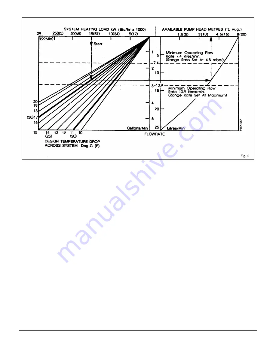
Pump Performance Curve
The circulating pump fitted within the appliance should be
capable of satisfying most system requirements. For central
heating systems greater than 15kW it may be necessary to
use a higher "design temperature drop across system" to
meet the system pump head requirement. The design
temperature drop should not exceed 20°C (36°F). Fig. 9
indicates the amount of pump head available for the system.
The boiler resistance is already taken into account in this
curve.
HOW TO USE FIG. 9.
Starting with the required SYSTEM HEATING LOAD, draw a
vertical line downwards so that it intersects the chosen
SYSTEM DESIGN TEMPERATURE DROP line, normally
this would be 11°C (20°F) although up to 17°C (30°F) can be
used without increasing radiator sizes. From this intersection
point draw a horizontal line so that it intersects the PUMP
CURVE. From this intersection draw a vertical line upwards.
The AVAILABLE PUMP HEAD can now be read from the
horizontal scale, and the corresponding FLOW RATE from
the vertical scale in the centre of the chart.
The system must be designed so that its hydraulic
resistance does not exceed the available head unless an
additional circulating pump is fitted.
If the designed flow rate through the boiler is less than 11.5
l/min, the boiler could be noisy and ultimately overheat. See
note on system by-pass in Section 1.5.
Central Heating Range Rate
For most installations the boiler will automatically adjust the
central heating output to match your heating system
requirement.
Systems which have very low water content and a low
heating requirement may benefit by reducing the maximum
boiler output. This is achieved by rotation of the adjustment
knob, located on the electronic modulation control board.
(Fig. 30).
The boiler central heating output can be adjusted between
the maximum and minimum values stated on the data
badge. Operation of this adjuster will not affect the maximum
boiler output when domestic hot water is being drawn off.
Summary of Contents for 80e
Page 5: ...Optional Extras Page 5 ...
Page 6: ...Optional Extras Page 6 Installation instructions included as necessary with each kit ...
Page 7: ...Optional Extras Page 7 Installation instructions included as necessary with each kit ...
Page 12: ......
Page 28: ...Routine Maintenance Page 27 ...
Page 30: ...Routine Maintenance Page 29 ...
Page 34: ...Component Replacement Page 33 ...
Page 35: ...Component Replacement Page 34 ...
Page 43: ...7 1 Control Flow Sequence Permanent Pilot Page 42 ...
Page 44: ...7 2 Functional Flow Permanent Pilot Page 43 ...
Page 45: ...7 3 Fault Finding Permanent Pilot Page 44 ...
Page 46: ...7 4 Electrical Diagram Permanent Pilot Page 45 ...
Page 47: ...8 1 Control Flow Sequence Electronic Page 46 ...
Page 48: ...8 2 Functional Flow Electronic Page 47 ...
Page 49: ...8 3 Fault Finding Electronic Page 48 ...
Page 50: ...8 4 Electrical Diagram Electronic Page 49 ...


