Boiler Installation - Page 18
2.5
Pressure Relief Valve
The pressure relief valve is pre-set at 3 bar.
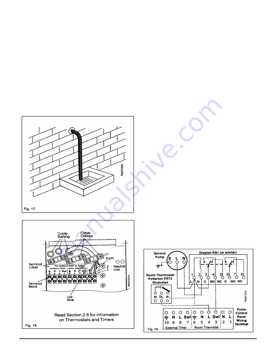
Install a pressure relief valve discharge pipe, not less than
15 mm diameter and connect to the pressure relief outlet
connection using a 15mm Compression fitting. The pipe run
should be as short as possible, run continuously downwards
and discharge to the outside of the building, where possible
over a drain. The pipe end should be directed towards the
wall. (Fig. 17) The discharge point must be such that it will
not be hazardous to occupants or cause damage to external
electrical components or wiring.
IT MUST NOT DISCHARGE ABOVE AN ENTRANCE, OR
WINDOW, OR ANY TYPE OF PUBLIC ACCESS. THE
INSTALLER MUST CONSIDER THAT THE OVERFLOW
COULD DISCHARGE BOILING WATER.
Read Section 2.6 for information on Thermostats and Timers
2.6
Wiring the Appliance
The internal wiring of the appliance is shown in Figs. 42 & 46
. The wiring diagram is also on the inside of the front casing
panel.
a) Undo the single retaining screw on the top of the controls
panel and allow the panel to swing down.
b) Using PVC insulated cable of not less than 0.75 mm².
(24/0.2mm to BS 6500 Table 16), wire up the panel
referring to the termination label. (Fig. 18).
Note:
Ensure that all cables pass through the wiring panel
bush/s and are securely fixed by the cable clamp/s.
If a room thermostat is to be fitted, remove the Red link wire
between terminals 3 and 4 and discard prior to wiring in the
thermostat. If no room thermostat is to be fitted retain link
wire.
If a programmable room thermostat is to be used it must be
fitted in place of the external timer and the link between 3 &
4 retained.
If the installation does not have an internal or external timer
the central heating switch on the front of the appliance must
be set to Constant during periods when central heating is
required.
If using an internal timer connect the timers lead to PL11 on
the modulation control board. (Fig. 30).
If an external frost thermostat is required it should be
connected to terminals 3 and 8. For the frost thermostat to
function the boiler switch must be set to 'On'.
Secondary Pump
.
If a second pump is to be fitted to the
central heating system it should be sited on the return to the
boiler and electrically connected using a proprietary relay as
shown in Fig. 19.
c)
Check all wiring and reposition the control panel.
d)
Secure with screw provided.
Note:
The electrical mains supply must be fused at 3 A, and
the connection must be made to the wiring panel in such a
way that should the lead disengage from the cable clamp,
the current carrying conductors become taut before the earth
conductor.
Summary of Contents for 80e
Page 5: ...Optional Extras Page 5 ...
Page 6: ...Optional Extras Page 6 Installation instructions included as necessary with each kit ...
Page 7: ...Optional Extras Page 7 Installation instructions included as necessary with each kit ...
Page 12: ......
Page 28: ...Routine Maintenance Page 27 ...
Page 30: ...Routine Maintenance Page 29 ...
Page 34: ...Component Replacement Page 33 ...
Page 35: ...Component Replacement Page 34 ...
Page 43: ...7 1 Control Flow Sequence Permanent Pilot Page 42 ...
Page 44: ...7 2 Functional Flow Permanent Pilot Page 43 ...
Page 45: ...7 3 Fault Finding Permanent Pilot Page 44 ...
Page 46: ...7 4 Electrical Diagram Permanent Pilot Page 45 ...
Page 47: ...8 1 Control Flow Sequence Electronic Page 46 ...
Page 48: ...8 2 Functional Flow Electronic Page 47 ...
Page 49: ...8 3 Fault Finding Electronic Page 48 ...
Page 50: ...8 4 Electrical Diagram Electronic Page 49 ...


