Commissioning - Page 23
3.6
D.H.W Flow Rate
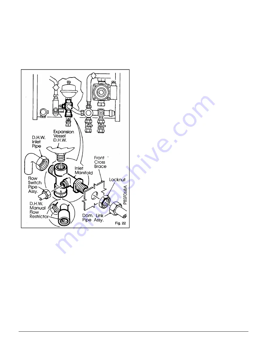
The appliance contains an automatic flow regulator
supplying a nominal flow rate of 12 litres/minute (100 &
100e). These flow rates will give a nominal temperature rise
of 35°C. Should it be desired to set the appliance to give a
higher temperature rise, the flow rate can be further reduced
by using the manual flow restrictor (clockwise to reduce)
located in the manifold below the mini expansion vessel -
Fig. 22.
3.7
Central Heating
a)
Ensure that all external controls such as a timers are
switched On and that room thermostat/s are calling for
heat.
b)
Set the Central Heating switch to Timed (if system fitted
with Timer) or Constant. The appliance will operate in
accordance with the pre-selected temperature set on the
lower temperature control knob.
3.8
Temperature Controls
a)
Central Heating
The lower control knob enables you to control the
temperature of the central heating flow as it leaves the
appliance. This knob can be set between the - and + setting.
The graduations correspond approximately to a temperature
of 60°C to 79°C. Under a minimum load
condition the flow temperature can rise to 87°C at maximum
setting. The appliance is fitted with a Central Heating switch
which will allow you to switch Off the central heating during
the summer months (mid position).
b) Hot Water
The upper control knob enables you to control the
temperature of the domestic hot water as it leaves the
appliance. The knob can be set between the - and + setting.
The graduations - to + correspond approximately to a
temperature of 45°C to 65°C.
3.9
Appliance Protection Devices
Loss of gas supply, flame failure, or over-heating of the
central heating water will cause the appliance to shut down
or Lockout.
On the 100 model (with permanent pilot) this will be
indicated by the pilot being extinguished. To restart the
appliance follow the lighting instructions on the boiler facia
label or as shown in Section 3.3.
On the 100e model (electronic) this will be indicated by the
lockout light being illuminated. To Reset the appliance press
the RESET button on the front panel and hold in that position
for 10 seconds and release. The appliance should now
operate normally.
If this is not the case refer to the Fault Finding guide either
on the rear of the white front case or pages 39 & 48 of these
instructions.
If the central heating system looses pressure for any reason
the appliance will cease to function and the Low System
Pressure light will illuminate. The system and the appliance
should be checked for leaks (including discharge from the
pressure relief pipe). Correct any faults and re-pressurise the
system with reference to Section 1.6. Mains Water Feed
Central Heating.
All models are fitted with a Frost thermostat which will bring
the appliance On when the local temperature around the
appliance falls below 5°C The appliance will shut down when
the temperature of the system water has been raised by
approximately 10°C
The appliance is protected provided the Mains light is
illuminated and the Boiler switch is set to On (and on
permanent pilot models the pilot is alight), irrespective of the
settings of any external controls.
Note:
the Frost thermostat will operate with the central
heating switch in any position therefore when leaving the
property in cold weather for extended periods, the boiler will
be protected even when the switch is set to Off (Mid
position).
Note:
While the appliance is being used to provide hot water
at any draw off point, the central heating will not operate.
When hot water is no longer required the appliance will
automatically revert to central heating.
Summary of Contents for 80e
Page 5: ...Optional Extras Page 5 ...
Page 6: ...Optional Extras Page 6 Installation instructions included as necessary with each kit ...
Page 7: ...Optional Extras Page 7 Installation instructions included as necessary with each kit ...
Page 12: ......
Page 28: ...Routine Maintenance Page 27 ...
Page 30: ...Routine Maintenance Page 29 ...
Page 34: ...Component Replacement Page 33 ...
Page 35: ...Component Replacement Page 34 ...
Page 43: ...7 1 Control Flow Sequence Permanent Pilot Page 42 ...
Page 44: ...7 2 Functional Flow Permanent Pilot Page 43 ...
Page 45: ...7 3 Fault Finding Permanent Pilot Page 44 ...
Page 46: ...7 4 Electrical Diagram Permanent Pilot Page 45 ...
Page 47: ...8 1 Control Flow Sequence Electronic Page 46 ...
Page 48: ...8 2 Functional Flow Electronic Page 47 ...
Page 49: ...8 3 Fault Finding Electronic Page 48 ...
Page 50: ...8 4 Electrical Diagram Electronic Page 49 ...


