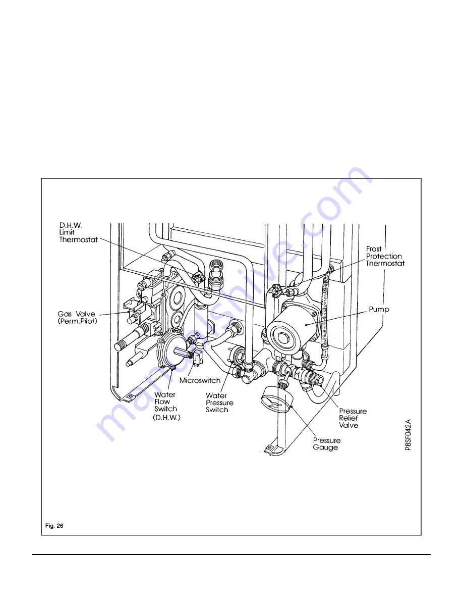
6. Component Replacement - Page 30
WARNING:
Before attempting to remove any component from this appliance, first disconnect the mains electricity supply by
removing the plug from the wall socket or by switching off the appliance at the external isolating switch.
Note:
The appliance
stand-by switch must not be used as the means of isolating, as this switch does leave parts of the appliance electrically live.
IMPORTANT:
After removal or replacement of any gas carrying components a test for gas soundness must be made.
Notes
: The appliance gas supply should be isolated at the boiler gas service cock (one quarter turn of square spindle).
The Central Heating and Domestic Hot Water circuits can similarly be isolated at their respective valves. A drain
point is provided in the appliance heating circuit under the pump manifold and the cold water inlet isolating valve
also incorporates a drain screw. Use a suitable tube when draining to direct water away from the appliance.
When removing any water carrying components suitably protect the control box from accidental spillage.
Before removing any component from the central heating circuit on the appliance, reduce the pressure by closing
the isolating valves and opening the pressure relief valve.
Summary of Contents for 80e
Page 5: ...Optional Extras Page 5 ...
Page 6: ...Optional Extras Page 6 Installation instructions included as necessary with each kit ...
Page 7: ...Optional Extras Page 7 Installation instructions included as necessary with each kit ...
Page 12: ......
Page 28: ...Routine Maintenance Page 27 ...
Page 30: ...Routine Maintenance Page 29 ...
Page 34: ...Component Replacement Page 33 ...
Page 35: ...Component Replacement Page 34 ...
Page 43: ...7 1 Control Flow Sequence Permanent Pilot Page 42 ...
Page 44: ...7 2 Functional Flow Permanent Pilot Page 43 ...
Page 45: ...7 3 Fault Finding Permanent Pilot Page 44 ...
Page 46: ...7 4 Electrical Diagram Permanent Pilot Page 45 ...
Page 47: ...8 1 Control Flow Sequence Electronic Page 46 ...
Page 48: ...8 2 Functional Flow Electronic Page 47 ...
Page 49: ...8 3 Fault Finding Electronic Page 48 ...
Page 50: ...8 4 Electrical Diagram Electronic Page 49 ...


