Component Replacement - Page 41
Note:
The outlet of the pressure relief valve is an olive
connection.
d.
Fit the new pressure relief valve using a new ‘O’ ring
seal and soap solution as a lubricant. Re-assemble in
reverse order.
e.
Recharge the system as described in section 1.6 and
check for leaks.
6.30
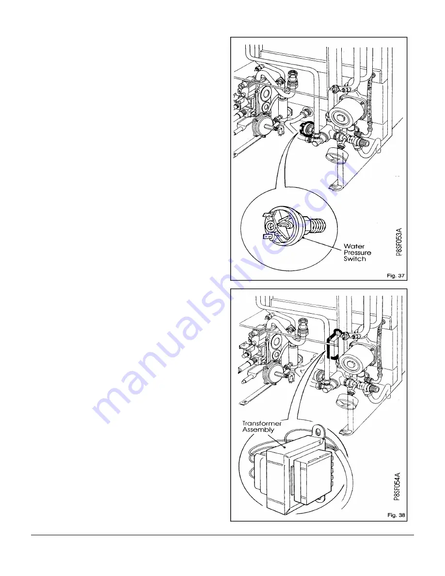
Water Pressure Switch
(Fig. 37)
a.
Remove the white front case and base panel.
See 5.1 & 5.2 in 'Routine Maintenance'.
b.
Close the central heating isolating valves, reduce the
system pressure by opening the pressure relief valve,
then drain the water from the appliance by removing the
drain off screw on the underside of the pump manifold.
c.
Lower the control panel assembly by undoing the
securing screw at the top right hand side of this control
panel.
d.
Remove the two wire connections and unscrew the
switch from the diverter valve.
e.
Fit the new switch using a new sealing washer.
f.
Re-assemble in reverse order. Electrical polarity is not
important. If there are three terminals, do not use the
terminal insulated by sleeving.
The wires must be connected to the terminals on the
switch body marked 1 & 2. (Normally Closed)
g.
Open the isolating valves. Re-charge the system as
described in section 1.6 and check for leaks.
6.31
Transformer Assembly
(Fig. 38)
a. Remove the white front case and base panel.
See 5.1 & 5.2 in ’Routine Maintenance’.
b.
Lower the control panel assembly by undoing the
securing screw at the top right hand side of the control
panel.
c.
Remove the transformer wiring loom from the retaining
cable ties and unplug the connector to the electronic
control board PL 6 (top right hand side of control board).
Thread the wiring out of the control panel.
d.
Remove the two screws retaining the transformer to the
back panel and remove transformer from appliance.
e.
Fit the new transformer assembly in reverse order.
6.32
Sight Glass With Securing Frame
a.
Remove the white front case, base panel and air box
main cover. See 5.1, 5.2 & 5.3 in ‘Routine Maintenance’.
b.
On the inside of the inner door straighten the four
retaining tags. Remove sight glass.
c.
Renew the sight glass and use a new gasket to seal.
d.
Re-assemble in reverse order.
Summary of Contents for 80e
Page 5: ...Optional Extras Page 5 ...
Page 6: ...Optional Extras Page 6 Installation instructions included as necessary with each kit ...
Page 7: ...Optional Extras Page 7 Installation instructions included as necessary with each kit ...
Page 12: ......
Page 28: ...Routine Maintenance Page 27 ...
Page 30: ...Routine Maintenance Page 29 ...
Page 34: ...Component Replacement Page 33 ...
Page 35: ...Component Replacement Page 34 ...
Page 43: ...7 1 Control Flow Sequence Permanent Pilot Page 42 ...
Page 44: ...7 2 Functional Flow Permanent Pilot Page 43 ...
Page 45: ...7 3 Fault Finding Permanent Pilot Page 44 ...
Page 46: ...7 4 Electrical Diagram Permanent Pilot Page 45 ...
Page 47: ...8 1 Control Flow Sequence Electronic Page 46 ...
Page 48: ...8 2 Functional Flow Electronic Page 47 ...
Page 49: ...8 3 Fault Finding Electronic Page 48 ...
Page 50: ...8 4 Electrical Diagram Electronic Page 49 ...


