20
Note: Before any maintenance is carried out on the system, ensure that the electrical supply has been
disconnected first. Care must be taken as the water may be scalding hot and at high pressure.
Maintenance on the boiler can only be carried out by a qualified and competent tradesman in
accordance with supplied instructions.
Removal of the Main Power PCB
Switch OFF electrical supplies to the boiler. Both Main, “Live and Neutral”, and Control “R and N”
1.
must be isolated
Remove the front top panel.
2.
Disconnect the control PCB and carefully remove the high temperature insulation and the front
3.
bottom panel.
Unplug the control connector (Conn1), the temperature switch connector (Conn3), and the
4.
thermistor connector (Conn4).
Unplug the power connectors on the elements.
5.
Disconnect the main power cable to Conn5.
6.
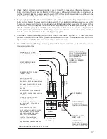
Remove the 4 screws identified by the black triangles, see figure sixteen below.
7.
Carefully remove the PCB assembly from the pipework. This may be stiff and gentle prising at
8.
the top may be required.
Replacing the Main Power PCB
Ensure heat sink compound is used on the heat sinks.
1.
Identify and plug the power connectors onto the elements, colour for colour, as it is easier to
2.
make these connections before fitting the PCB.
Holding the back plate line up the pillars with the PCB and position it onto the pipework.
3.
Loosely add the 4 fixing screws.
4.
Tighten up these screws in the order shown below in figure sixteen. It is important to ensure that
5.
the PCB assembly is tight on the pipework.
Reconnect connectors (Conn1, 3 & 4)
6.
Reconnect the control PCB and replace the high temperature insulation.
7.
Ensure the main power connections are tight. Loose connections can cause a fire.
8.
REPLACING THE MAIN POWER PCB
1
2
3
4
FIGURE SIXTEEN: MAIN POWER PCB


