POTTERTON COMMERCIAL PRODUCTS DIVISION
SECTION 4
INSTALLATION, OPERATION & MAINTENANCE MANUAL
PAGE 15
ISIS HE
6. Open the drain-cock and drain the boiler.
Remove the blanking plates. Connect the flow
and return 3” – 4” BSP extension turrets to the
boiler (8 – 14 Section only).
Boiler Dismantling
IMPORTANT: THE BOILER SECTIONS ARE NOT
SELF SUPPORTING PARTICULARLY WHEN
THERE ARE ONLY TWO OR THREE SECTIONS
LEFT IN SITU. THEREFORE DURING
DISMANTLING THE SECTIONS SHOULD BE
SUPPORTED TO PREVENT INJURY TO
OPERATIVES.
Dismantling of the boiler is a reversal of the erection
procedure as previously detailed. Care should be
taken during dismantling due to the weight of the
sections and should be carried out by two operators
at a time.
Fitting the Casing
To allow fitting of the electrical and fuel services it will
be necessary to fit casing panels as detailed in the
paragraphs 1 – 12 below, the flue spigot as
paragraph 19 and the burner as detailed under
relevant section. However, the remaining casing and
insulation can, if required, be fitted after construction
has ceased in the boiler house to minimise damage
to the casing.
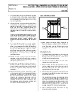
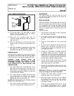
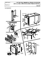
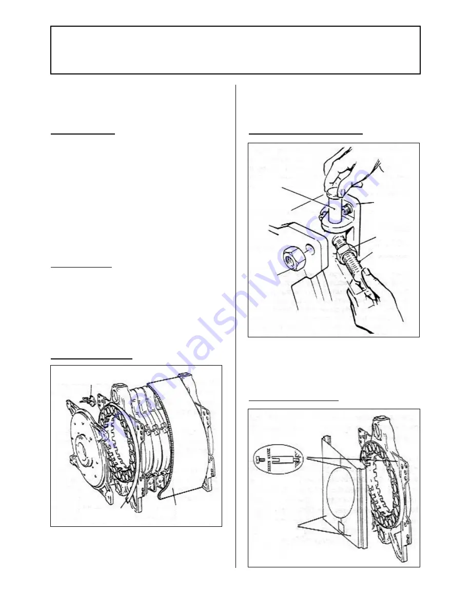
Fig.7 – Boiler Insulation
1. Fit the insulation strip to the front section as
shown in Fig.7 and secure in position using the
adhesive tape provided.
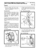
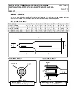
2. Fit firing door support brackets to the front face of
the boiler, together with four studs and securing
pins. Fit locknuts to the studs on the door hinge
side, see Fig.8
Fig.8. – Fitting Locknuts to Studs
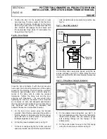
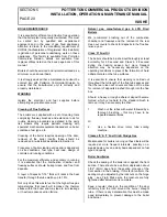
3. Fit the eight hexagonal spacers to the front
section and fit the front boiler casing. This is a
two piece construction using eight machine
screws provided, see Fig.9.
Fig.9. – Front Panel Fixing
Front Door Support
Bracket
Front Insulation Strip
Boiler Body
Insulation
Fixing
Nut
Securing
Pin
Firing Door
Support
Bracket
Lock Nut
Hinge Stud
Fixing Spacer
Two Piece
Front Casing
Summary of Contents for Isis HE
Page 1: ...MAY 2004 ...


