© Baxi Heating UK Ltd 2008
41
Thermi
s
tor Fault - Flow and Ca
s
ting
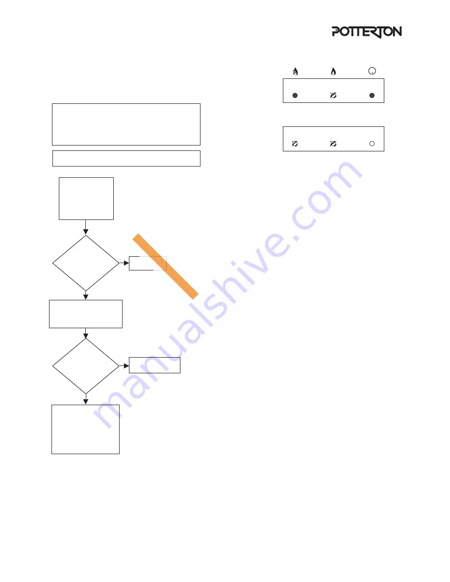
Refer to the boiler wiring diagram
Casting thermistor fault
Lockout Burner Mains
Flow thermistor fault
Lockout Burner Mains
No
Yes
Replace PCB
No
Yes
Check that the Pump is running and there is
adequate circulation of water.
Unplug the 12 way
connector to the PCB
Measure resistance
between the 2 blue
wires (casting thermister)
and the 2 yellow wires
(flow thermister)
Are the
resistances
between
0.5k
Ω
- 20k
Ω
and within
25% of
each other
Remove connectors
from the thermistors
Measure resistance
of thermistors
Do
resistances
vary from ones
previously
measured
Wiring from PCB
to thermistor faulty
Replace Faulty Thermistor
---------------------
This can be identified by
removing both thermistors
and holding the brass
probe between your fingers
The resistance should be
approximately 8k
Ω
There are two types of fault which can occur:
1) The thermistors are reading outside of limits (this is checked before
the PUMP is switched on and during Burner on).
2) The difference between the thermistor readings are outside of
limits (this is checked during PUMP on stage).
on
on
flashing
flashing
off
flashing
Fig. 49


