Publication No. 5106226
20
MAX0022C
-
+
PROG
SEL
PROG
SEL
-
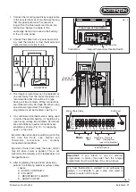
C.H. ADVANCE
H.W. TEMP
RESET
BURNER
LOCK OUT
MAINS ON
POWER
+
RWC
This Appliance
Must Be Ear
thed
N
L
N
F HW HW CH CH
T
T
R
L
L
R
R
L
R
2
L
2
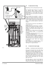
Fill up the Condensate
Trap with water, then
fit to the boiler
Condensate
Drain Pipe
500mm supplied
(suitable for 21.5mm
overflow pipe)
Washer Seal
Boiler
Condensate
Connection
Optional
Route -
DHW
Optional
Route -
Condensate
Fig. 12
Installation
2.5
Condensate Drain Pipe
Before fitting, fill the condensate trap with water.
The condensate pipe should be run in 21.5/22.0
mm diameter plastic material suitable for
operation at 60° C. Solvent weld PVC overflow is
recommended or a PP system can be used.
Copper tube must not be used. Do not use push-
fit plastic pipe.
Use the flexible pipe provided to connect to
21.5mm PVC pipe; alternatively a Marley or
Plumb Center elbow can be used to direct the
condensate pipe through the LH side panel (see
Fig. 12). When using the Osma PVC overflow
system, a 3/4 -to-22mm adaptor No. 158 may be
required.
Internal pipework should have a bore diameter no
smaller than 14 mm.
External pipework should be kept to a minimum,
and have a bore diameter no smaller than 32 mm.
Ideally the condensate pipe should be run
internally to the house soil and vent stack or to a
waste pipe.
Alternatively, the condensate may be discharged
into the rainwater system, or a purpose-built
soakaway.
All connecting drainage pipework must have a fall
of at least 50 mm per metre run.
It is recommended that the pipe is insulated if run
externally to minimise the effects of freezing, and
that a plastic insert is fitted that provides a
siphon/weir action to encourage the water to flow
in intermittent bursts rather than dripping
continuously.
Note: Connection of a condensate pipe to a drain
may be subject to local building regulations.
See Page 19 for a typical example.
2.6
Connect the Power Supply
WARNING – THIS BOILER MUST BE EARTHED
Wiring must comply with the current IEE Wiring
Regulations. The supply cable must be 3-core
0.75sq. mm (24/0.2 mm) to BS6500 Table 16.
The supply must be of 230V – 50Hz. A 3A-fused
double pole-isolating switch may be used, having
a minimum contact separation of 3 mm in both
poles, providing it serves only the boiler and its
system controls. Alternatively a 3A 3 pin fused
plug may be used.
The wiring diagram is shown in Fig. 25, Page 36.
Note that the boiler control is fitted with two
internal 3.15A “slow blow” fuses (20 mm x 5 mm).


