Publication No. 5106226
29
Powermax
-
+
SEL
SEL
-
+
MAIN
S ON
POW
ER
CH
HW
PRO
G
PROG
C.H. A
DVAN
CE
H.W. TE
MP
RES
ET
BUR
NER
LOC
K OU
T
Isolating
Valve
Closed
Open
Isolating
Valve
Pump
Isolating
Valve
Disconnect
Pump
Connector
Remove Expansion
Vessel Support Bracket
Bulkhead
Push Fit Elbow
Metal Washers
2 Fibre
Washers
Lift Out
Pump
Pump
Bottom
Pipe
Pump Top
Pipe
Pull
forward
Expansion
Vessel
Disconnect
Flexible Pipe
Washer
Washer
Pressure Relief
Valve
Loosen when removing pump
complete
MAX0015C
Disconnect
Pump
Connector
Rotate Pump
to Access
the Pump
Motor
Pump
Motor
Remove 4
Securing Screws
Open
Auto
Air
Vent
Cap
Open Pressure
Relief Valve
Expansion Vessel
Gas Cock
Isolating Valve
4.3
Expansion Vessel/Pump
Re-assemble all parts in reverse order.
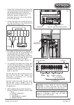
1. Perform 4.1 General Access. Also remove
the moulded facsia panel (2 screws).
2. Isolate three valves as shown and open
the cap on the auto air vent.
3. Release pressure by opening the
pressure relief valve.
4. Remove expansion vessel
Remove securing screws and support
bracket. Disconnect flexible pipe at the
vessel. Pull vessel forwards and out of the
boiler.
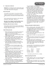
5a.
Pump Motor
Loosen the top pipe union nut at the
pump.
Disconnect electrical connector from the
pump motor. The pump can now be
rotated so the motor retaining screws can
be removed
5b.
Pump Complete
Disconnect the top pipe union nut at the
pump. Disconnect electrical connector
from the pump motor. Loosen 22 mm
compression nut on cross fitting, lift the
pump up and it will disconnect (complete
with pipe) from the push fit elbow.
Important:
Ensure that the metal washer
is located between the push fit elbow and
the bulkhead and also above the rubber
washers on top of the bulkhead. This will
ensure that the pump can be easily
removed in the future.
Fig. 18
Replacement of Parts


