Publication No. 5106227
2
Flueing
This is a “room sealed” condensing appliance.
Flue
systems are supplied in kits, or components can be
ordered individually from Potterton. Only Powermax flue
components (which are designed for condensing
operation) can be used.
Flue Systems
All appliances are supplied to accept the Powermax 60
mm dia. twin flue system, however several flue system
options are available.
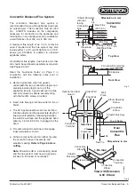
Each system is room sealed and offers a choice of flue
type and termination method, see Fig. 2.
• Concentric balanced flue with horizontal terminal
• Twin flue with vertical terminal *
• Twin flue with pitched roof terminal *
• Twin flue with horizontal mini terminal
Flue kits are available for each of the above options and
each kit contains all of the components needed for
connection to the appliance and terminal.
Flue
extension lengths and bends should be purchased
separately, as required.
* These terminals must be ordered/specified separately.
Flue Protection
When using an extended flue system it is essential to fit
protective ducting (such as that supplied in the extended
flue kits) in order to prevent direct contact with the hot
flue pipe, See Page 7.
General Requirements for Horizontal Flue
Terminations
Detailed recommendations for flueing are given in
BS5440: Part 1. The following notes give general
guidance. The horizontal balanced flue terminal must be
installed so that it is exposed to external air, preferably
on a clear expanse of wall. Acceptable positions are
indicated in Fig. 3. Avoid positions where the terminal is
adjacent to projections; particularly immediately under a
balcony, inside a re-entrant position, or immediately
adjacent to a drain pipe. If the appliance is fitted under
a ventilator or opening window, the terminal must be at
least 300 mm from any part of the window or ventilator
and in accordance with BS5440: Part 1.
The flue pipe must not be closer than 25 mm to
combustible material. Additional clearance must be
provided when passing the flue through timber walls.
Advice on gas installations in timber framed buildings is
contained in IGE technical publication IGE/UP/7
available from the Institution of Gas Engineers, 21
Portland Place, London W1N 3AF.
Guidance notes for Flue Installation
Read these Installation Instructions before installing
the boiler
. Before starting an installation, check that the
correct flue kit has been supplied with the boiler.
Detailed recommendations for flue installations are given
in BS 5440:1: 2000. The following notes are for general
guidance only.
a) The flue system must be constructed using only
Powermax approved components.
b) It is important that the position of the terminal allows
free passage of air across it at all times.
c) It is ESSENTIAL TO ENSURE that products of
combustion discharging from the terminal cannot re-
enter the building, or any other adjacent building,
through ventilators, windows, doors, other sources of
natural air infiltration, or forced ventilation / air
conditioning.
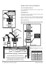
d) The minimum acceptable dimensions from the flue
terminal to obstructions and ventilation openings are
specified in Figs. 3 & 4 on Page 4 of these instructions.
e) If the flue terminal discharges into a pathway or
passageway check that combustion products will not
cause nuisance and that the terminal will not obstruct
the passageway.
f) Where terminals are fitted within 850 mm of a plastic
or painted gutter, or 450 mm of painted eaves, an
aluminium shield at least 750 mm long must be fitted
to the underside of the plastic or painted surface.
g) Where installation will be in an unusual location,
special procedures may be necessary. BS 6798 gives
detailed guidance on this aspect.
h) As the Powermax is a condensing appliance the flue
duct must have a generous fall back to the boiler of
nominally 2°.
j) The efficient condensing operation of the Powermax
HE will naturally give rise to condensation in the flue
gases and
pluming will occur in all but the most
favourable atmospheric conditions
. Some
condensate may also be discharged from the terminal.
The terminal must, therefore, be
sited to avoid
nuisance from either phenomenon
.
k) Where the lowest part of the terminal is less than 2 m
above the level of any ground, balcony, flat roof or
place to which people have access, the terminal must
be protected by a guard of durable material. A Terminal
Guard, Part No. P210 is available from Potterton. The
guard requires a flat wall surface of approximately 330
mm diameter, concentric with the terminal assembly.
Flueing


