Publication No. 5106227
11
MAX0042A
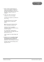
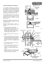
Flat Roof Flashing
Felt Roof
Ø180
Top Felt Layer
Bitumen
100mm Felt Collar
Bottom Felt
Roof Construction
Flat Roof Flashing
Asphalt Roof
Ø180
Apply sealant to
the edge such as
butyl or mastic
before fitting terminal
Asphalt
Roof Construction
Note:
Damage to the seals could result in
condensate/flue products leakage from the flue
system.
Note:
Due to the high efficiency and reduced
flue gas temperature of the Powermax HE, little
or no buoyancy is generated in a vertical length
of the 60 mm Ø flue pipe and installations
should therefore be designed with this in mind.
Fixing Flat Roof Flashing
Installation of the flat roof flashing unit must be
carried out by a competent flat roofing contractor.
The following notes are for the contractor’s
guidance. Avoid locating the flat roof flashing in a
position where standing water is likely to
accumulate.
For built up felt roofs, see Fig. 13.
1. Cut 180 mm diameter service opening through
roof construction and first layer of felt.
2. Bed flange of unit on to felt with bitumen.
3. Dress top layer(s) of felt over flange of unit.
4. Star cut a hole in the top-most layer and finish
by detailing a 100 mm high felt collar around
upstand.
5. Apply a butyl or mastic sealant around the
spigot on the flashing unit and carefully lower
the terminal into position, ensuring that the
spigot seats securely inside the terminal rim.
6. From inside the building fit the 131 mm
diameter pipe support bracket around the
projecting flue pipe and screw flanges to
support timber or structure. Ensure flue
terminal is positively secured and vertical.
For Asphalt Roofs, see Fig. 14.
1. Cut 180 mm diameter service opening through
roof construction and sheathing felt and firmly
locate the flashing unit in position over it.
2. Dress asphalt over aluminium flange and up
neck offset of flashing unit ensuring it does not
move from location.
3. Apply a butyl or mastic sealant around the
spigot on the flashing unit and carefully lower
the terminal into position, ensuring that the
spigot seats securely inside the terminal rim.
4. From inside the building fit the 131 mm
diameter pipe stabilising bracket around the
projecting flue pipe and screw flanges to
supporting timber or structure. Ensure flue
terminal is vertical and positively secured.
Fig. 13
Fig. 14
Flashing Kits - Flat & Pitched Roof


