Publication No. 5106227
14
Installing Mini Terminal Flues
Mark the positions of the air/flue terminals and core drill 70
mm (2¾) diameter holes.
If the wall is clad with a
combustible material an additional 25 mm wide area must
be removed around flue liner.
With care it is possible to core drill from inside and maintain
a clean, undamaged hole on the outside wall, but where
damage to the outside wall occurs this must be made good
to ensure a satisfactory weather seal when terminals are in
position. Terminals should be inserted through the wall
liner from outside to facilitate weather sealing.
a. Measure the wall thickness and cut the liner to this
length. Cut plain end opposite flange.
b. Fit the liner through the hole making good internal and
external rendering where necessary. Apply ‘mastic’ type
sealant to the last 25 mm of the liner behind the flange
(or to the outer part of the core-drilled holes) prior to
fitting liner to help make a weather seal between the
liner and the external leaf of the wall.
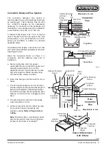
c. Slide the stainless steel cone along the terminal pipe,
followed by the large flexible seal as indicated in Fig.
19. Apply high temperature (red) silicone sealant to
ensure the terminal is weather sealed to the liner.
d. Working from outside the property, push the mini
terminal through the liner until the large seal is correctly
positioned against the outside wall.
e. Centralise flue pipe in liner using spacer if required.
Slide the internal wall plate over terminal pipe and
secure to wall using the plugs and screws provided.
Tighten clip to secure terminal.
Note:
Make any final adjustment to the position of the
external seal before tightening clip.
Assembling Air/Flue Pipes
Refer to Guidance Notes on Pages 6 & 7.
The flue pipes must be assembled with the plain end of
pipe or fitting nearest the boiler and the female (socket)
end furthest from the boiler. Check that a seal is fitted in
every socket.
Always adjust length of pipes by cutting and de-burring
plain end so that it does not damage or disturb the seal.
Remove burrs from inside and outside of pipe and ensure
the pipe is clean and free from oil and grease.
Any generally “horizontal” run of flue pipe MUST NOT
FORM A LOW POINT at which condensate could
accumulate.
a. Measure and cut the first pair of flue pipes away from
the appliance. Push pipes fully into the sockets on top
of the boiler whilst also fitting the flue duct prepared as
above.
b. Measure and cut next pair of air/flue pipes.
c. Prepare pipe support brackets as required before
engaging pipes with the socket of preceding pipes or
bends.
d. Push pipes together as before taking care not to
dislodge seals. When cutting and fitting flue pipes on
extended flue systems, allow approx. 5 mm clearance
at the bottom of each joint - see Fig. 7.
e. Repeat above procedure to reach terminal. Ensure
that air inlet and flue gas connections are correctly
made and are not inadvertently reversed.
f. Fix pipe supports to masonry or woodwork so that
flue/air pipes are held securely in position.
g. Check especially that all joints within any duct or other
void are correctly engaged and sealed before fixing
the ductwork.
MAX0044A
Wall Plate
&
Clamp
Inner
Wall
Outer
Wall
Terminal
Outer Wall
Plate
Flexible
Seal
Wall Liner
(Cut to length
Top
View
of
Boiler
92˚
Bend
Extension
MAX0038A
135˚
Bend
92˚
Bend
Extension
(cut to 443)
150˚
Bend
92˚ Bend
Air
Flue
Air
Flue
Extension
from boiler
135˚ Bend
Side
View
360
Twin Flue
Mini
Terminals
(Lefthand)
150˚ Bend
Extension
Air
Flue
360
minimum
30˚
offset
443 Nominal
Length (minimum)
Fig. 19
Fig. 20
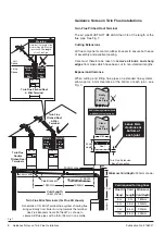
Twin Flue with Horizontal Mini Terminal


