background image

Publication No. 5106228

4

User’s Instructions

Things you need to be aware of

Air Locks

The boiler pump is fitted with an automatic air vent and
will bleed air from the boiler when required.

To access the bleed screw for this vent, pull off the top
front cover, remove the small inner panel and the
screw cap is situated just below the opening. Unscrew
by no more than one turn when air in the system is
suspected. e.g. after replacing a radiator. Tighten
screw again after 24 hours.

C.H. System Pressure

The Status Display window shows the actual water
pressure in the central heating system. It will drop
slightly when the central heating starts and will rise by
anything up to 1.5 bar as the central heating reaches
full temperature.

We recommend that the system pressure, when cold
be between 1.0 and 1.5 bar. If the pressure is falling,
the status display will flash 

‘P 0.9’ or lower and it is

advised to top up at this stage

. If the pressure drops

below 0.5 bar the boiler will not light, the status display
will show  ‘P 0.4’ or 'A 15’ and it will be necessary to
top up the pressure.

To top up:

Pull bottom panel off front of boiler and

connect filling loop to valve on cold water inlet. Open
both valves slowly and allow pressure to rise. Close
valves, disconnect filling loop and re-fit bottom panel.

If regular topping up is needed get your installer to
check the system for leaks

.

Severe loss of system pressure is indicated by 'A 15'
on the display and the red 'Lockout' neon will be on.
Top up as above then press the ‘Reset’ button, this will
reset the boiler and it should now light.

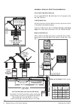
Flue

This exits through the roof or outside wall. Ensure it
does not become obstructed, particularly by foliage or
snow. Due to the high efficiency of the boiler and the
resulting low flue gas temperature, a plume of white
condensate may be emitted from the flue outlet 
terminal. This will be particularly noticeable during cold
weather and does not indicate a problem with the
boiler.

The flue pipe becomes very hot when the boiler is
operating. If the pipe is visible (such as in a loft space)
it is important that no flammable materials are allowed
to come into contact with the pipe.

Freezing Conditions

If the water temperature within the boiler drops below
5 °C, a sensor operates and runs the burner to keep
the water from freezing. This will only operate if the
electricity supply to the boiler is ON. If you are away

during periods of cold weather we recommend leaving
your boiler on and adjusting your control system (e.g
thermostat) to suit.

Condensate Outlet Pipe

If this has been run externally, it may drip water. This is
perfectly normal. Steps should be taken to prevent the
outlet freezing in very cold weather.

Safety Discharge Pipe

Ask your installer to identify the discharge pipe from
the pressure relief valve. Normally no water is vented
but scalding water and steam may be emitted and
indicate a fault condition. Switch off the boiler and call
your Installer.

Precautions should be taken to prevent the outlet
becoming blocked and to minimise the hazard to
persons (especially children) where the pipe
discharges.

Cleaning

The outer case parts can be wiped down with a damp
cloth to remove any marks. Do not use abrasive
cleaning agents as they may damage the finish on the
case parts.

Other controls

These may be fitted within the system e.g. room
thermostat. Full instructions on their use should have
been supplied with them.

In an Emergency

Gas

- In the event of a gas leak turn off the supply at

the isolating cock. If the leak is in the pipe from the gas
meter then turn off the isolating cock at the meter as
well. Call your gas supplier immediately.

Electricity

- The boiler can be isolated from the mains

supply by removing the plug from the socket or
switching the fused supply off.

Central Heating system

- If a radiator, pipe or the

boiler starts leaking, set the boiler On/Off Switch to
‘Off’ as this will stop the pump from working and will
minimise loss of water. Reference can be made to the
Installation & Servicing Instructions on how to remove
the outer casing and close the isolating cocks to the
central heating flow and return.

Hot Water

- If a hot water pipe starts to leak, set the

boiler On/Off Switch to ‘Off’, turn off the mains water
supply at the stopcock and collect the water in a
suitable container, 

take care, it could be 

Very Hot

.

(Remember to switch on any supplies you have closed once the
problem has been corrected).

Summary of Contents for Powermax HE 115

Page 1: ...ions Failure to install appliances correctly could lead to prosecution Installation must be in accordance with the Installation Service Instructions and the rules in force Read these Instructions before installing or lighting the boiler Leave these Instructions and the Benchmark Log Book with the user for use on future calls Installation Servicing Instructions Powermax HE 85 115 150 Litre Condensi...

Page 2: ...389 17 Important Refer to Page 8 for Storage Unpacking and Handling Instructions Benchmark Installation Commissioning and Service Record Log Book Potterton is a member of the Benchmark initiative and fully supports the aims of the programme Benchmark has been introduced to improve the standards of installation and commissioning of central heating systems in the UK and to encourage the regular serv...

Page 3: ...l Diagram Serial Number Data Badge Location Dowels Top Bottom Section Handholds Handholds Underneath boiler Lifting and plumbing access each side Mains power supply and Immersion Heater cable entry holes Pull up and away Top Panel 2 4 3 Pull forward Front Panel at the bottom and lift off General Access Plumbing Access 1 Pull forward Bottom Panel Unscrew Upper Panel at the bottom and pull away Reta...

Page 4: ...sion relief valve set 8 0 bar Filling Loop 15 mm 1 2 union accessible behind lower front panel Secondary Expansion Vessel 18 litre pre charge 2 5 2 7 bar supplied separately Automatic bypass Built in Pressure loss warning Linked to diagnostic display Built in programmer 2 channel pre programmed back lit display battery back up Separate times for HW CH advance button CH off selector External progra...

Page 5: ... POWER CH CH HW HW PROG PROG SEL SEL PROG PROG SEL SEL C H ADVANCE C H ADVANCE H W TEMP H W TEMP RESET RESET BURNER BURNER LOCK OUT LOCK OUT MAINS ON MAINS ON POWER POWER CH CH HW HW SEL SEL SEL SEL PROG PROG PROG PROG BURNER BURNER LOCK OUT LOCK OUT RESET RESET POWER POWER MAINS ON MAINS ON C H ADVANCE C H ADVANCE H W TEMP H W TEMP 150 litre model 115 litre model 85 litre model Concentric Flue 10...

Page 6: ...nologies Limited a United Kingdom Notified Body The range is certified to comply with the essential requirements of the Gas Appliance Directive 90 396 EEC the Low Voltage Directive 72 23 EEC and shows compliance with the Electro Magnetic Compatibility Directive 89 336 EEC the Boiler Efficiency Directive 92 42 EEC and are therefore permitted to carry the CE Mark Operation The boiler control works o...

Page 7: ...ring Regulations Where no specific instructions are given reference should be made to the relevant British Standard Codes of Practice In IE the installation must be carried out by a Competent Person and installed in accordance with the current edition of I S 813 Domestic Gas Installations the current Building Regulations and reference should be made to the current ETCI rules for electrical install...

Page 8: ... front and gas supply pipework of not less than 22 mm diameter should be run to the boiler The meter and supply pipes must be capable of delivering this quantity of gas in addition to the demand from any other appliances in the house and must be governed at the meter The gas installation should be in accordance with the relevant standards In GB this is BS 6891 In IE this is the current edition of ...

Page 9: ... Requirements If floor settlement is likely due to the weight of the boiler ensure that both the flueing and pipework layouts safely provide sufficient flexibility If the boiler is to be fitted in a room containing a bath or shower reference must be made to the relevant requirements In GB this is the current I E E Wiring Regulations and Building Regulations In IE reference should be made to the cu...

Page 10: ...ows free passage of air across it at all times c It is ESSENTIAL TO ENSURE that products of combustion discharging from the terminal cannot re enter the building or any other adjacent building through ventilators windows doors other sources of natural air infiltration or forced ventilation air conditioning d The minimum acceptable dimensions from the flue terminal to obstructions and ventilation o...

Page 11: ...t 135 Bend Extension Mini Terminal sited in loft Pitched Roof Terminal 135 elbow fitted 600 mm min apart 360 mm min apart Twin Pitched Roof Terminals can be fitted Air Pipe Flue Pipe Flue Duct Pitched Roof Flashing Flat Roof Flashing Reducer Ø80 to Ø60 1 5m min to 12m max Mini Terminal Air Pipe Flue Pipe Flue Duct 92 Bend 135 Bend 92 Bend Extension Extension 92 Bend 1m min to 12m max Adaptor Box A...

Page 12: ...balconies or car port roof G From a vertical drain pipe or soil pipe H From an internal or external corner I Above ground roof or balcony level J From a surface facing a terminal K From a terminal facing the terminal L From an opening in a carport e g door window into the dwelling M Vertically from a terminal on the same wall N Horizontally from a terminal on the same wall R From adjacent wall to ...

Page 13: ... grade polyphosphates can be effective in reducing limescale but require correct siting and regular replenishment to remain operational They should generally not be fitted where heat could impair their perfomance Other types of device can inhibit scale formation but their effectiveness may vary The manufacturers of any water conditioning device should be consulted regarding its suitability for the...

Page 14: ...max HE The discharge pipe D2 from the tundish should terminate in a safe place where there is no risk to persons in the vicinity of the discharge preferably be of metal and a be at least one pipe size larger than the nominal outlet size of the safety device unless its total equivalent hydraulic resistance exceeds that of a straight pipe 9m long i e discharge pipes between 9m and 18m equivalent res...

Page 15: ...h discharges Worked example of discharge pipe sizing The example below is for a G1 2 temperature relief valve with a discharge pipe D2 having 4 No elbows and length of 7 m from the tundish to the point of discharge From Table 1 Maximum resistance allowed for a straight length of 22mm copper discharge pipe D2 from a G1 2 temperature relief valve is 9 0 m Subtract the resistance for 4 No 22 mm elbow...

Page 16: ...ondensate trap 3 Move boiler into position The need to move as Top and Bottom sections or as a complete assembly will depend on the individual installation The Top has 4 downward facing dowel pins which provide accurate location on to the cylinder Take care to avoid trapping hands and fingers during assembly 4 Apply sealant to cone faces of both 22mm Union Nuts see Fig 10 Remove cardboard pipework...

Page 17: ...alve Schraeder Valve Primary Expansion Vessel Wiring Cover Auto Air Vent Pump Control Box D H W Outlet Primary Pressure Sensor D H W Outlet Pressure Relief Valve 3 bar TPR Valve Temperature Pressure Relief By pass Valve Isolating Valve Isolating Valve Tundish Discharge Pipe Pressure Gauge Pipework shown as this NOT SUPPLIED Filling Loop Potterton Powermax HE 150 litre model shown Mains Cold Inlet ...

Page 18: ...Control Group and the expansion vessel can be sited away from the boiler e g to supply reduced pressure to all the system but it is essential that no valve is fitted in line between the store and either of these components Solder Flux Use water soluble flux for making soldered capillary joints in the primary circuit Traditional grease based flux containing zinc chloride must not be used CH System ...

Page 19: ...p Nut Washer Threaded Rod Washer Nut Wall Bolts Plugs MAX0003D Schematic ONLY Discharge Pipes can be combined as shown Floor CH Flow Gas CH Return Cold feed to showers only Pipework shown as this NOT SUPPLIED 400mm Ø240mm PROG SEL PROG SEL C H ADVANCE H W TEMP RESET BURNER LOCK OUT MAINS ON POWER RWC This Appliance Must Be Earthed N L N F HW HW CH CH T T R L L R R L R 2 L2 Inlet Control Group set ...

Page 20: ...to a minimum and have a bore diameter no smaller than 32 mm Ideally the condensate pipe should be run internally to the house soil and vent stack or to a waste pipe Alternatively the condensate may be discharged into the rainwater system or a purpose built soakaway All connecting drainage pipework must have a fall of at least 50 mm per metre run It is recommended that the pipe is insulated if run ...

Page 21: ...ctor is longer than the blue neutral and brown live conductors Secure the cable to the anchorage clamp and route via the bushing in the L H side panel 2 Connect the cable from any external control e g room thermostat or frost thermostat and route via lower LH side of unit 3 The integral programmer can be replaced by one sited away from the boiler if required It is recommended that it should be of ...

Page 22: ...l cutout which cuts the power to the immersion heater in an overheat situation Should this operate it can be manually reset by pressing the red button to the side of the temperature adjustment dial Note Investigate the cause of the overheating prior to resetting Should the immersion heater require replacement use only the Powermax spare part P3223 5106143 2 8 How to Drain Hot Water Storage Cylinde...

Page 23: ...tem pressure e g P 1 5 in bar or The selected temperature of the DHW e g U 55 in C or The flow temperature to the CH circuit e g c 80 in C by pressing the reset button to scroll from one display to the next The Programmer Display Window shows time of day and when implemented is used for setting and checking the timed on periods MAX0010A D H W ON Indicator Light Green Mains ON Indicator Light Amber...

Page 24: ... G C H ADVANCE H W TEMP RESET BURNER LOCK OU T MAX0001C Flue Test Point Heat Exchanger Return Sensor Overheat Thermostat Flow Sensor Air Manifold Burner Assembly Fan Assembly Spark Generator Diverter Valve PCB Controls Assembly Manual Air Vent Bleed Remove to add inhibitor Isolating Valve Ignition Electrode Isolating Valve Expansion Vessel E Vessel Schraeder Valve Pressure Relief Valve Air Gas Val...

Page 25: ...free spindle if it appears to be sticking Air should be expelled from auto air vent and the control display will warn if system pressure falls below 0 5 bar Top up if required Loosen bleed screw for pump spindle to remove air and re tighten 10 Use the programmer CH and HW buttons to alternately select central heating and hot water Observe that indicator on diverter valve moves forward hot water an...

Page 26: ... selected temperature After filling with cold water this will normally take between 20 to 25 minutes 4 With flow to the CH circuit bleed every radiator and the pipework high points until all air or air water mix has been removed 5 Vent the boiler again if necessary note that the burner control goes to safety shut down if the system pressure drops below 0 5 bar 6 Wait until the central heating circ...

Page 27: ...that the strainer is correctly located 6 With no water pressure in the system check and if necessary adjust the secondary expansion vessel pressure to approx 2 5 to 2 8 bar 36 to 40 psi Note Vessel pressure can not be accurately set with water pressure in system 7 Restore pressure to DHW system Manually operate in turn the expansion relief valve part of Inlet Control Group and the temperature pres...

Page 28: ...hing off the boiler at the external isolating switch Warning The fan operating voltage is 325V d c Take appropriate precautions Allow at least 40 seconds to elapse before handling the PCB within the boiler control assembly Important After removal or replacement of any gas carrying component a test for gas soundness must be made and functional check of the controls carried out Important Any O rings...

Page 29: ...ve the moulded facsia panel 2 screws 2 Isolate three valves as shown and open the cap on the auto air vent 3 Release pressure by opening the pressure relief valve 4 Remove expansion vessel Remove securing screws and support bracket Disconnect flexible pipe at the vessel Pull vessel forwards and out of the boiler 5a Pump Motor Loosen the top pipe union nut at the pump Disconnect electrical connecto...

Page 30: ...art of the complete cross unit and cannot be replaced separately Remove the pressure relief valve as shown above then release the unions and remove the cross unit Powermax SEL SEL MAIN S ON POW ER CH HW PRO G PROG C H ADVA NCE H W TEMP RESE T BUR NER LOC K OUT Expansion Vessel Pull out Clip to release Pressure Relief Valve Remove Primary Pressure Sensor O Ring Disconnect Electrical Connector Press...

Page 31: ... spanner to nip the screws when in position 5 Fan Disconnect the electrical connections at the fan Remove the 3 bolts securing the fan to the venturi and the 4 screws and nuts securing the fan to the burner Carefully lift the fan out and away from the boiler Be careful not to lose the large O ring between the fan and venturi Inspect and if necessary replace gasket behind the fan outlet flange Tran...

Page 32: ... screws securing the spark generator to its bracket ensure earth wire is re connected on re assembly 3 Ignition Electrode Carefully disconnect the earth lead at the electrode Remove the screws securing the electrode to the heat exchanger Carefully remove the electrode from the heat exchanger On re assembly check that the spark gap between the tips is 3 5 4 0 mm 3 Ionisation Probe Carefully disconn...

Page 33: ...cia Remove Front Fascia Securing Screws Side Support Spark Generator Location Peg 4 8 Boiler Control Assembly Warning The fan operating voltage is 325V d c Take appropriate precautions Allow at least 40 seconds to elapse before handling the PCB within the boiler control assembly Re assemble all parts in reverse order 1 Perform 4 1 General Access 2 Isolate the electricity supply to the boiler 3 Rem...

Page 34: ...1 General Access Refer to Fig 24 Page 35 2 Disconnect electrical connections and unscrew the thermostat Polarity of the wires is not important 4 11 Diverter Valve Complete Manual Air Vent Temperature Flow Return Sensors Re assemble all parts in reverse order 1 Perform 4 1 General Access 2 Check that the boiler primary system is isolated from mains water supply 3 Release pressure from primary syste...

Page 35: ...ng Part No 5106807 will be helpful in reinstating extended twin pipe flue systems Re assemble all parts in reverse order 1 Perform 4 1 General Access 2 Check that the boiler primary system is isolated from the mains water supply Release pressure from the primary system and drain down 3 Remove expansion vessel pump gas valve fan venturi diverter valve and heat exchanger door complete with burner al...

Page 36: ... C1176 C1212 C1206 BL BL BL BL BL BL BL BK BK BK BK BK BR BL BL BL R R R R BR W W BK R R Y Y BL BL W W BK HIGH VOLTAGE CONNECTIONS NOTE ALL CONNECTIONS ARE VIEWED FROM THE CABLE ENTRY SIDE KEY G Y GREEN YELLOW W WHITE G GREEN BL BLUE BL BLACK BR BROWN R RED O ORANGE Y YELLOW V VIOLET P PURPLE P H C 129 R2 CONTROL UNIT MAINS OUTSIDE SENSOR ROOM STAT FROST STAT INTERNAL FUSE NOTE NOT TO BE CHANGED B...

Page 37: ... L L R R L R 2 L2 J1 J6 JP3 Insulation Mains Cable Clip Terminal Connector 12 way Earth Point Boiler Control Box Bottom Connectors Cover Plate Securing Screw Diverter Valve Cable Spark Generator Ignition Electrode Cable Ionisation Probe Cable Fan Cable Ignition Electrode Earth Gas Valve Earth Gas Valve Overheat Thermostat Cable Temperature Return Sensor Temperature Return Flow Sensor Cable Tempera...

Page 38: ...iler Control Change fan MAX0056A YES YES YES YES YES YES NO NO NO NO NO NO Check gas supply Check gas valve 240v JP2 BL BK YES YES Change gas valve YES NO Check overheat stat NO Replace coil NO Check dial gauge pressure 1 2 9 bar Check sensor for damage blockages electrical connections etc replace as necessary Recharge replace vessel to 1 bar NO NO NO NO YES Check condensate trap is NOT blocked Re...

Page 39: ...Press RESET button to scroll display E 01 Primary pressure too high Reduce CH system pressure Check adjust replace primary expansion vessel 5106287 E 03 Flow temperature abnormally high Check pump 3 way valve CH system pressure Replenish system adjust pump speed bleed air E 04 Flow sensor open circuit Check cable connections not damaged Renew sensor cable Check connections on control E 06 Flow sen...

Page 40: ...Publication No 5106226 40 7 Short List Of Spare Parts Fig 27 Short List of Spare Parts MAX0046A 22 20 23 16 19 17 24 15 6 13 10 11 9 8 4 5 1 2 3 7 12 21 14 18 8 9 ...

Page 41: ...t 2 screws 1 5106941 10 E83 476 HT Lead 1 5106284 11 E83 477 Ionization Lead 1 5106285 12 E85 752 3 Way Valve Assembly Body O Rings Clips key no 13 1 5106931 13 E85 753 Actuator Head 1 5107000 14 E85 761 Pump c w auto air vent 2 off washers 1 5106286 E85 762 Automatic Air Vent 1 5106932 15 E83 481 Expansion Vessel 12 Litre Primary 1 5106287 16 E83 482 PRV Assembly 1 5106288 17 E83 483 Immersion NT...

Page 42: ... screw from flue gas outlet above heat exchanger and insert probe of combustion analyser approximately 50 mm Temporarily seal probe into flue gas test point 3 Press ADVANCE or central heating SELECT button to obtain ON display in programmer screen Ensure any connected room thermostat is calling for heat Observe burner lights and allow boiler to operate in central heating mode for several minutes 4...

Page 43: ... other than this use throttle adjustment screw to obtain correct setting Note Turning screw clockwise reduces CO2 anti clockwise increases CO2 Ensure fan does not modulate by maintaining a CH or DHW demand during the above sequence As a double check the expected CO content should be in the range of 65 to 85 ppm when CO2 is 9 1 Check that gas rate is approximately 2 55 m3 hr 9 Replace dust cover re...

Page 44: ...re sold subject to our standard Conditions of Sale which are available on request General Enquiries GB Tel 08706 060 780 Sales GB Tel 08706 060 403 Fax 01772 695 416 Technical GB Tel 08706 060 955 Service GB Tel 08706 060 933 Fax 08706 060 966 Literature Request GB Tel 08706 060 623 Spares GB Tel 08706 000 454 Technical IE Tel 1850 560570 BAXI POTTERTON A Trading Division of Baxi Heating UK Ltd Br...

Page 45: ...Systems Powermax HE 85 115 150 Litre Condensing Boilers with Integrated Hot Water Storage These instructions cover the installation of the following kits and their options Concentric Flue Horizontal Terminal Page 5 Twin Flue Vertical Terminal Page 10 Twin Flue Pitched Roof Terminal Page 12 Twin Flue Mini Horizontal Terminal Page 13 Contents General Flue Guidance Pages 1 to 4 Concentric Kit Page 4 ...

Page 46: ... Gas Engineers 21 Portland Place London W1N 3AF Guidance notes for Flue Installation Read these Installation Instructions before installing the boiler Before starting an installation check that the correct flue kit has been supplied with the boiler Detailed recommendations for flue installations are given in BS 5440 1 2000 The following notes are for general guidance only a The flue system must be...

Page 47: ... Pipe Ø60 Flue Pipe Ø60 Flue Duct 135 Bend Extension Mini Terminal sited in loft Pitched Roof Terminal 135 elbow fitted 600 mm min apart 360 mm min apart Twin Pitched Roof Terminals can be fitted Air Pipe Flue Pipe Flue Duct Pitched Roof Flashing Flat Roof Flashing Reducer Ø80 to Ø60 1 5m min to 12m max Mini Terminal Air Pipe Flue Pipe Flue Duct 92 Bend 135 Bend 92 Bend Extension Extension 92 Bend...

Page 48: ... Directly below an opening air brick opening window etc B Above an opening air brick opening window etc C Horizontally to an opening air brick opening window etc D Below a gutter or sanitary pipework E Below the eaves F Below a balcony or carport roof G Above ground roof or balcony level H From vertical drain soil pipe work J From an internal or external corner K From a surface facing a terminal L...

Page 49: ...ue pipe into flue outlet on top of boiler c The 90 appliance elbow can now be fitted into the adaptor and the appropriate length of flue pipe calculated by measuring between the outside wall face and the appliance bend allowing 45 mm to 55 mm to engage into the bend d Fit outer wall seal to terminal and engage inner wall plate as shown e All flue components contain rubber lip seals to ensure both ...

Page 50: ...Terminals 7m Flue Kit shown Ø60 1 5m Schematic of 7m Mini Terminal flue system showing flue rising vertically from boiler rising towards the terminal Use Flue Brackets from kit 5106257 as shown to secure Air Flue pipes with a fall of 35mm in one metre 1950mm 1950mm Flue Brackets Void Length 5 5m shown Seal Leave 5mm clearance at bottom of each joint Guidance Notes on Twin Flue Installations Twin F...

Page 51: ...hort 1 off C Flue Pipe Cover Long 1 off D Fixings Pack 1 off not shown A B C Flue Duct This kit covers pipe lengths from 0 5 m to 1 45 m 1 Measure length of flue air pipes to be covered Set the short and long covers to the required length and secure through the relevant holes using four of the self tapping screws provided 2 Attach the pipe clip brackets to the top and bottom of the covers using th...

Page 52: ...135 Bends 1 Fixing Rail 0 5m Twin Flue Pitched Roof Kit Pitched Roof Terminal 25 45 Part No 5106164 4 5m Twin Flue Pipe Kit for Pitched Roof Term Part No 5106259 3 Threaded Rods 1m x M8 6 Pipe Clamps Ø60 4 Extensions 0 5m x Ø60 4 Extensions 1m x Ø60 4 135 Bends 3 Fixing Rails 0 5m Pitched Roof Terminal Mini Terminal MAX0029B 500mm 1 x Flue Bracket Pack 4 Locking Nuts 2 Slide Nuts 2 Wood Screws 2 W...

Page 53: ...0 2 Extensions 1m x Ø60 2 Extensions 0 5m x Ø60 Flue Pipe 1 5m x Ø60 Flue Duct 2 92 Bends 150 Bend 2 Fixing Rails 0 5m 1 Fixing Rail 0 5m 2 Mini Terminals 2 Wall Liners 2 Wall Plates Clamps MAX0030B 500mm 165 Bend Part No 5106277 Flue Bracket Pack 4 Locking Nuts 2 Slide Nuts 2 Wood Screws 2 Wall Plugs Flue Bracket Pack Part No 5106207 Twin Flue Pipe Kits for Mini Terminals 3m 5m Part Number 3m ill...

Page 54: ...sion air flue pipes and bends to enable the terminal to be sited up to 2 5 m from the boiler The maximum overall length of the complete flue system must not exceed the limits shown in Fig 2 Page 3 All additional flue lengths flue bends and other kits should be purchased separately as required See Pages 8 and 9 Read the Guidance Notes on Page 2 in conjunction with the following notes prior to insta...

Page 55: ... layer s of felt over flange of unit 4 Star cut a hole in the top most layer and finish by detailing a 100 mm high felt collar around upstand 5 Apply a butyl or mastic sealant around the spigot on the flashing unit and carefully lower the terminal into position ensuring that the spigot seats securely inside the terminal rim 6 From inside the building fit the 131 mm diameter pipe support bracket ar...

Page 56: ...ighest level of the ceiling insulation The Pipework Kit Part No 5106259 for the Pitched Roof Terminal is based on a nominal 4 5 m of twin flue This allows for example up to 5 m of flue pipe between boiler and flue terminal plus up to 4 m of air pipe between boiler and air terminal The flue pipe must not exceed 12 m in which case the air pipe must not be less than 9 m The minimum length of flue pip...

Page 57: ...llowing notes prior to installation a The Powermax HE is a condensing boiler and the flue system must have a generous fall back to the appliance nominally 2 and be adequately supported This will ensure the correct trouble free disposal of condensate produced in the flue during normal operation b All flue components contain rubber lip seals to ensure both ease of assembly and excellent sealing Refe...

Page 58: ...fer to Guidance Notes on Pages 6 7 The flue pipes must be assembled with the plain end of pipe or fitting nearest the boiler and the female socket end furthest from the boiler Check that a seal is fitted in every socket Always adjust length of pipes by cutting and de burring plain end so that it does not damage or disturb the seal Remove burrs from inside and outside of pipe and ensure the pipe is...

Page 59: ...Air Flue Pipe 0 25 m each 1 2 60 mm Air Flue Pipe 0 5 m each 2 1 60 mm Air Flue Pipe 1 0 m each 3 8 60 mm Air Flue Pipe 1 5 m each 5 5 60 mm Air Flue Pipe 2 0 m each 7 2 60 mm Air Flue Pipe 3 0 m each 10 6 Bend 92 4 0 Bend 135 45 Bend 3 4 Bend 150 30 Bend 2 6 Bend 165 15 Bend 1 4 Note The above component factors are to be cumulatively subtracted from the total system factor of 100 See Below Ensure...

Page 60: ...ailable on request To aid continuous improvement and staff training calls to this line may be monitored or recorded General Enquiries Tel 08706 060 780 Sales Tel 08706 060 403 Fax 01772 695 416 Technical Tel 08706 060 955 Service Tel 08706 060 933 Fax 08706 060 966 Literature Request Tel 08706 060 623 Spares Tel 08706 000 454 Publication No 5106227 Iss 04 07 2003 BAXI POTTERTON A Trading Division ...

Page 61: ...r fault lock out conditions are displayed as E number or A number see chart on Page 7 Note Please record the fault code and the boiler Serial No see page 8 when contacting the Service department Reset button Use this button to scroll display when setting the desired hot water temperature or checking status or pressure Use also to re start boiler after fault is repaired Amber neon indicates that th...

Page 62: ... later stage If it is known or suspected that a fault exists on the a ppliance it must not be used until the fault has been corrected by a competent person If a gas leak is suspected turn off the appliance and consult your local gas supplier or service engineer Flammable materials must not be stored in close proximity to the boiler Do not obstruct any purpose provided ventilation openings The mini...

Page 63: ...ler On Off switch to the O OFF position and isolate the gas supply at the boiler It may be advisable to contact your Service Engineer if you wish to do this How your boiler Works Control of the Boiler The boiler is fitted with a control panel which indicates basic functions and also contains a programmer If your installer has fitted another make of programmer remote from the boiler the programmer ...

Page 64: ...ls are allowed to come into contact with the pipe Freezing Conditions If the water temperature within the boiler drops below 5 C a sensor operates and runs the burner to keep the water from freezing This will only operate if the electricity supply to the boiler is ON If you are away during periods of cold weather we recommend leaving your boiler on and adjusting your control system e g thermostat ...

Page 65: ...described in Section 2 0 Page 6 To set up your own ON OFF times refer to Section 3 0 Page 6 If you wish to return to the built in time periods after changes have been made to them firstly ensure the programmer is in Normal Operation Section 1 0 Page 6 Then press hold down the and buttons together after 2 seconds or so release the two buttons and the built in periods will be active Using the HW and...

Page 66: ... Monday If you wish only to change the HW times press the SELECT button under the HW neon and it will start to flash Adjust using or Press STEP and OFF1 will flash Adjust using or 3 3 ON2 OFF2 ON3 OFF3 can be set by repeating the procedure shown for ON1 OFF1 3 4 Once OFF3 has been set press STEP and Tuesday will now flash 3 5 Repeat the procedure for Tuesday and all other days of the week 3 6 Once...

Page 67: ...ff boiler Call Powermax service A 19 Flame detection gas valve fault Switch off boiler Check replace gasvalve press RESET A 20 Flame detected with closed gasvalve Switch boiler off on Press RESET If repeated call Powermax service A 33 Fan speed incorrect Switch boiler off on Press RESET If repeated call Powermax service A 40 System response fault Open radiator valves if shut press RESET If repeate...

Page 68: ... 000 454 Technical IE Tel 1850 560570 Publication No 5106228 Iss 04 02 2004 BAXI POTTERTON A Trading Division of Baxi Heating UK Ltd Brownedge Road Bamber Bridge Preston Lancashire PR5 6SN Website www potterton co uk company Powermax SEL SEL MAINS ON POWE R CH HW PROG PROG C H ADVANC E H W TEMP RESET BURNE R LOCK OUT Cylinder Serial Number label on outside of bottom plinth Heat Engine Serial Numbe...

Reviews: