10.0 Installation
32
© Baxi Heating UK Ltd 2011
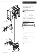
10.6
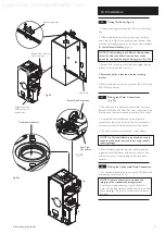
Making the Gas Connection
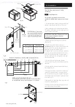
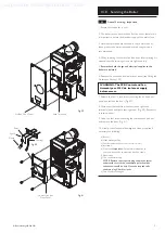
1. Connect the gas supply to the G
1
/
2
(
1
/
2
in BSPT
Internal) gas tap. This is located on the lower right side
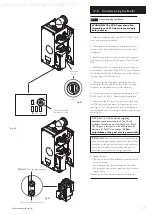
of the boiler, access by hinging down the PCB housing
(see Fig. 32).
10.7
Fitting The Flue
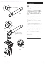
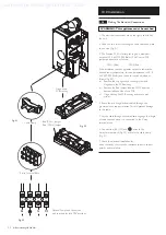
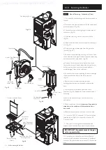
Before fitting the flue, check the condensate drain
integrity (see section 10.5).
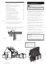
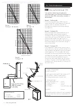
IMPORTANT: The flue should always be installed
with at least 1.5° fall from terminal to elbow, to
allow condensate to run back to the boiler.
HORIZONTAL FLUE
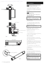
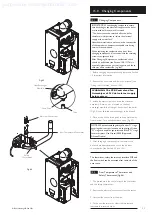
1. The standard flue is suitable for lengths 270mm
minimum to 800mm maximum (measured from the
edge of the flue elbow outlet).
Rear Flue:
maximum wall thickness - 630mm
Side Flue:
maximum wall thickness - 565mm (left or right)
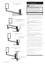
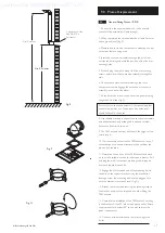
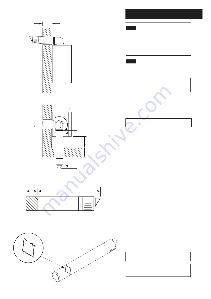
2.
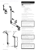
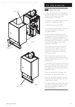
For rear exit
- measure the wall thickness
(Fig. 26) and to this dimension add 181mm. This
dimension to be known as (X).
i.e.
(X) = wall thi 181
3. Take the flue and mark off (X) from the terminal end
as indicated in the diagram (Fig. 27).
Check your dimensions.
The flue tubes are fixed together. Cut through both
tubes whilst resting the flue on the semi-circular packing
pieces. Deburr both tube ends.
4.
For side exit
- measure the distance from the edge
of the wall plate to the inner face of the wall (Fig. 26)
and to this dimension add the wall thi 250mm.
This dimension to be known as (Z).
i.e.
(Z) = wall plate to wall + wall thi 250
5. Take the flue and mark off (Z) from the terminal end
as indicated (Fig. 27).
Check your dimensions.
The flue tubes are fixed together. Cut through both
tubes whilst resting the flue on the semi-circular packing
pieces. Deburr both tube ends.
IMPORTANT: Check all measurements before
cutting.
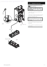
NOTE: When cutting ensure the cut does not
interfere with the inner flue support bracket
(Fig. 27a).
360° Orientation
Inner Flue Support Bracket
Wall Thickness
(Z)
Edge of Wall Plate to Wall
Wall Thickness
(Z) = Side Exit
(X) = Rear Exit
Flue
Waste
Fig. 26
Fig. 27
Fig. 27a
At Least 1.5°
Supplied by HeatingSpares247.com

