13.0 Changing Components
33
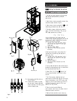
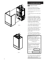
The control and ignition boards can be
accessed on the removal of the main
electrical box cover.
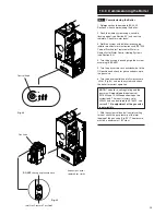
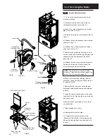
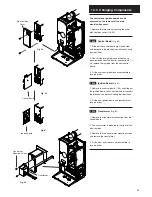
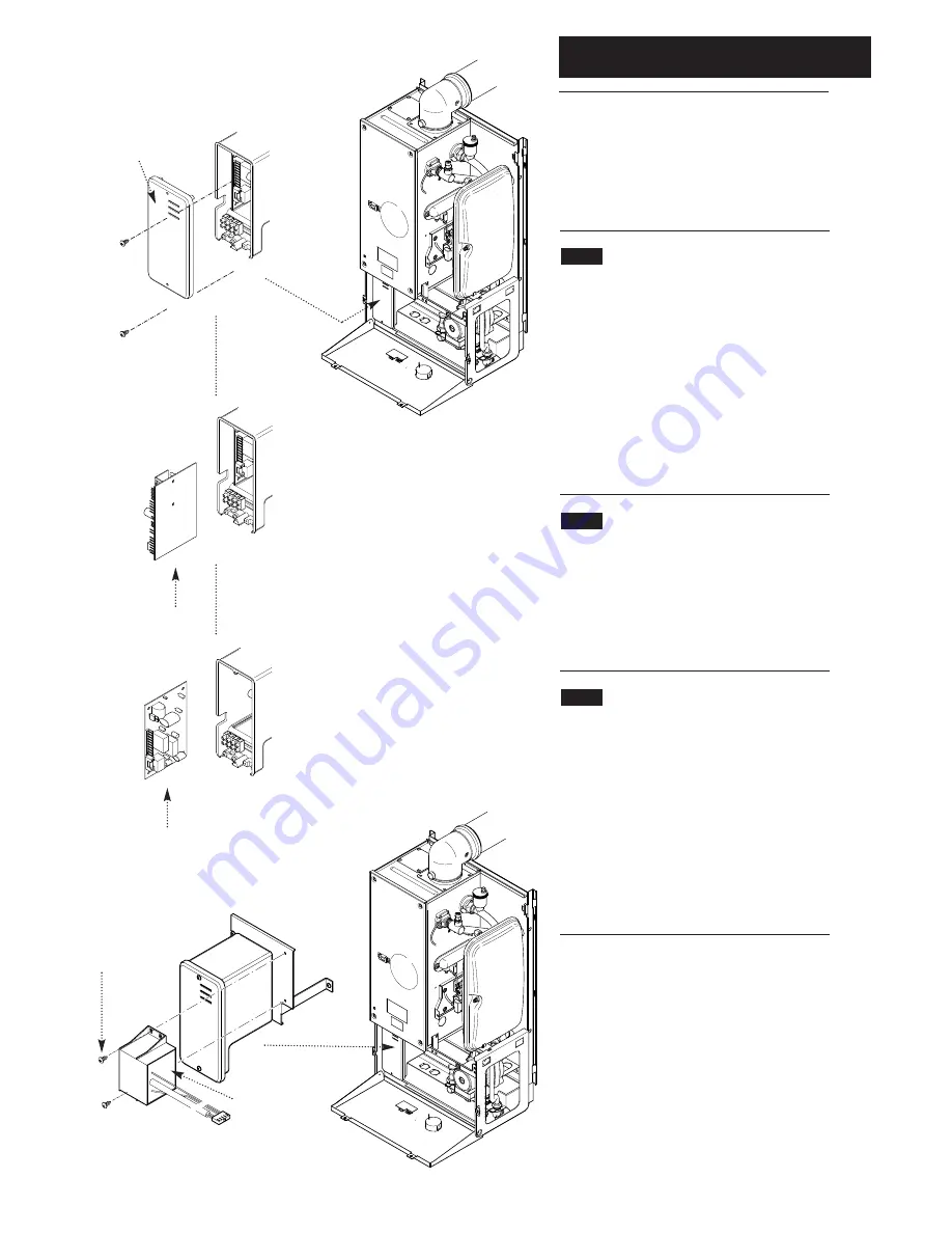
1. Remove the two screws securing the main
electrical box cover (Fig. 59).
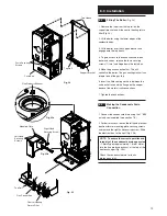
13.13
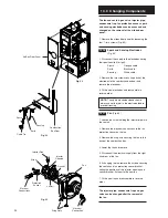
Control Board
(Fig. 60)
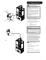
1. Slide out the control board (right hand side)
and disconnect the electrical connections noting
their positions.
2. Check if the two jumper connections have
been removed from the board - see section 8.7. If
so, remove the jumpers from the new control
board.
3. Fit the new control board and reassemble in
reverse order.
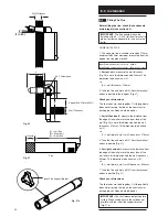
13.14
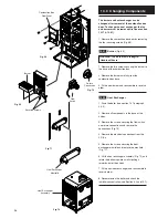
Ignition Board
(Fig. 61)
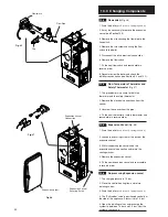
1. Remove the control board, (13.5) and slide out
the ignition board (left hand side) and disconnect
the electrical connections noting their positions.
2. Fit the new ignition board and reassemble in
reverse order.
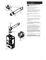
13.15
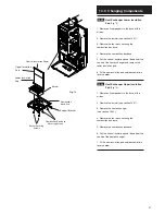
Transformer
(Fig. 62)
1. Remove the transformer connection from the
control board.
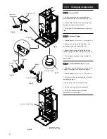
2. The transformer is mounted to the right of the
electrical box.
3. Remove the two transformer mounting screws
and remove the transformer.
4. Fit the new transformer and reassemble in
reverse order.
Fig. 59
Fig. 60
Fig. 61
Fig. 62
Control Board
Ignition Board
Electrical Box
Cover
Transformer
Transformer
Mounting Screws

