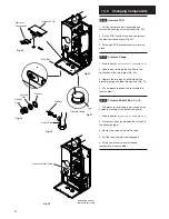
13.0 Changing Components
36
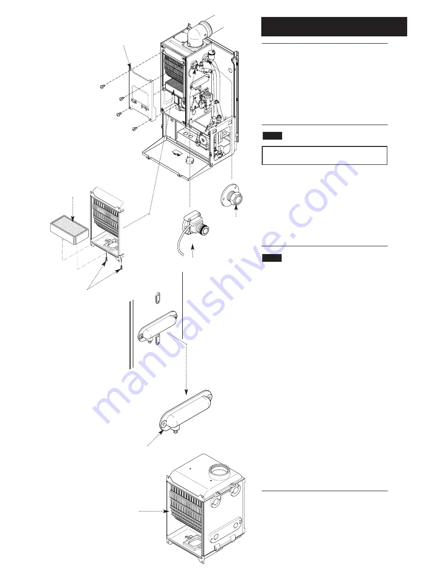
The burner and heat exchanger can be
changed after removal of the combustion box
door. To change the heat exchanger, the fan
and burner must be removed first (see section
13.17 & 13.21).
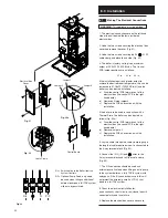
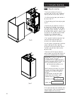
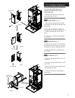
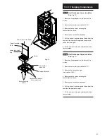
1. Remove the combustion box door by removing
the four securing screws (Fig. 68).
13.21
Burner
(Fig. 69)
WARNING: The burner skin is fragile:
Handle with care
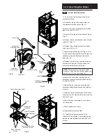
1. Remove the two screws securing the burner to
the base of the combustion box.
2. Remove the burner carefully from the
combustion box base.
3. Fit the new burner and reassemble in reverse
order.
13.22
Heat Exchanger
1. Drain the boiler (see section 13.1 paragraph
2 & 3).
2. Remove all components in the base of the
airbox.
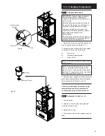
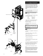
3. Remove the screws securing the flow switch
and return connections and remove the
connections (Fig. 70).
4. Remove the electrical connections from the
P.C.B.s.
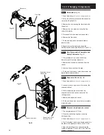
5. Remove the screws securing the heat
exchanger manifold and remove the manifold
(Fig. 71).
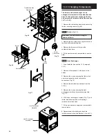
6. Lift the heat exchanger assembly (Fig. 72) and
rotate the bottom upwards whilst pulling it
forwards out of the airbox.
7. Fit the new heat exchanger and reassemble in
reverse order.
8. Recommission the boiler and check the
inhibitor concentration (see Section 6.2 and 10.1).
Combustion Box
Door Panel
Burner
Securing Screws
Fig. 68
Fig. 69
Fig. 71
Fig. 72
Fig. 70
Heat Exchanger
Manifold
Return
Connection
Flow
Switch
Heat Exchanger
Assembly

