38 Component Replacement
Part No. 27/20334
Component Replacement - Page 38
PROCEDURE 2
If the clearance above the appliance is
less than 300mm
the appliance must be removed from the wall.
a.
Remove the complete casing assembly (front, base
and sides)
b.
Close all the isolating valves, reduce the pressures in
the appliance by operating the pressure relief valve.
Drain the remaining water in the boiler by removing the
drain screws under the pump manifold (C.H.).
c.
Lower the control box assembly by undoing the
securing screws at the top of the control box.
d.
Disconnect the input wiring noting positions of wires
and thread wiring out of control panel grommet/s.
e.
Check the gas supply is isolated at the gas service
cock, (1/4 turn of square head), undo the gas cock
union nut and position nut clear of thread. Disconnect
the two flexible hoses from the boiler or tank. Take
care to collect any water remaining water in a
container.
f.
Undo the upper isolator valve connections on the C.H.
flow, return and Cold water inlet valves. Similarly
disconnect hot flow pipe, and pressure relief pipes.
g. Disconnect the flue elbow from the top of the
appliance, (4 screws), lift the flue elbow off the boiler
connection and rotate the elbow 180° to position the
flue clear of the appliance. If a vertical flue system is
fitted it will require raising approximately 50mm (2") to
allow the boiler to be lifted off its hanging screws.
h.
Remove the bottom boiler securing screw then loosen
the appliance upper securing screws and lift the boiler
off the wall. Place unit face downwards on the floor.
Care should be taken not to damage the pressure
gauge or electronics.
j.
Access can now be made to the expansion vessel.
Undo the flexible pipe connection to the vessel and
remove the screws retaining the upper expansion
vessel bracket to release the vessel from the
appliance.
k.
Fit a new expansion vessel and re-assemble in reverse
order, using a new sealing washer. At this stage it is
advisable to check the pre-charge.
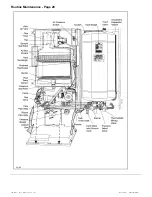
6.20
Heat Exchanger
(See Fig. 23).
a.
Perform 5.1 to 5.6 & 5.8 in ‘Routine Maintenance’.
Remove the combustion chamber insulation by
removing each side panel retaining screw and pulling
the complete side panel /insulation assembly forwards.
The rear insulation can remain in situ.
b.
Close all the isolating valves, reduce the pressures in
the appliance by operating the pressure relief valve.
Drain the remaining water in the boiler by removing the
drain screws under the pump manifold (C.H.). Undo
the heat exchanger connection to the auto air vent
pipe.
c.
Disconnect the electrical connections from the
overheat thermostat. The control box should be
protected from water spillage.
d.
Release the four spring clips retaining the heat
exchanger tails by pulling the clip forwards and
towards the centre of the appliance and ease the heat
exchanger up, out of the housings.
e.
The heat exchanger waterways can now be de-scaled
or a replacement heat exchanger can be fitted, in
which case the overheat thermostat must be
transferred to the new heat exchanger.
f.
Re-assemble in reverse order. Use a soap solution to
lubricate the new ‘O’ rings when fitting the new heat
exchanger, also, ensure the heat exchanger is pushed
fully down. Re-charge the system as described in
section 1.6 and check the joints for leaks.
Summary of Contents for Puma Flowsure+
Page 5: ...Part No 27 20334 Introduction 5 Introduction Page 5 ...
Page 28: ...28 Routine Maintenance Part No 27 20334 Routine Maintenance Page 28 ...
Page 30: ...30 Routine Maintenance Part No 27 20334 Routine Maintenance Page 30 ...
Page 34: ...34 Component Replacement Part No 27 20334 Component Replacement Page 34 ...
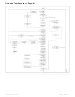
Page 42: ...42 Control Flow Sequence Part No 27 20334 8 Control Flow Sequence Page 42 ...
Page 43: ...Part No 27 20334 Functional Flow 43 9 Functional Flow Page 43 ...
Page 44: ...44 Pictorial Wiring Diagram Part No 27 20334 10 Pictorial Wiring Diagram Page 44 ...
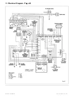
Page 45: ...Part No 27 20334 Electrical Diagram 45 11 Electrical Diagram Page 45 ...
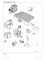
Page 47: ...Part No 27 20334 Short List of Spares 47 Short List of Spares Page 47 Back page ...

