Part No. 27/20334
Installation Requirements 7
Installation Requirements Page 7
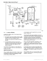
Fig 2
1.2
Location Of Boiler
In siting the combination boiler, the following limitations
MUST be observed:
a) The position selected for installation should be within
the building, unless otherwise protected by a suitable
enclosure. It must allow adequate space for
installation, servicing and air circulation around the
appliance.
b) This position MUST also allow the chosen flue
termination to be made correctly. The boiler must be
installed on a flat vertical wall which is capable of
supporting the weight of the appliance and any
ancillary equipment.
The appliance may be installed on a combustible wall,
subject to the requirements of the Local Authorities and
Building Regulations.
IMPORTANT NOTICE
If the combination boiler is to be fitted in a timber framed
building it should be fitted in accordance with the British
Gas publication 'Guide for Gas Installations in Timber
Frame Housing'. (Reference DM2).
If in doubt advice must be sought from the Local Gas
Region of British Gas.
The combination boiler may be installed in any room or
internal space, although particular attention is drawn to the
requirements of the current I.E.E. Wiring Regulations, and
in Scotland, the electrical provisions of the Building
Regulations applicable in Scotland, with respect to the
installation of the combination boiler in a room or internal
space containing a bath or shower.
Where a room-sealed appliance is installed in a room
containing a bath or shower, any electrical switch or
appliance control, utilising mains electricity should be so
situated that it cannot be touched by a person using the
bath or shower.
A compartment used to enclose the combination boiler
MUST be designed and constructed specifically for this
purpose. An existing cupboard, or compartment, may be
used provided it is modified accordingly. See Section 1.4
Air Supply.
Where installation will be in an unusual location, special
procedures may be necessary. BS 6798 gives detailed
guidance on this aspect.
Summary of Contents for Puma Flowsure+
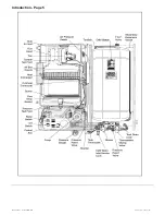
Page 5: ...Part No 27 20334 Introduction 5 Introduction Page 5 ...
Page 28: ...28 Routine Maintenance Part No 27 20334 Routine Maintenance Page 28 ...
Page 30: ...30 Routine Maintenance Part No 27 20334 Routine Maintenance Page 30 ...
Page 34: ...34 Component Replacement Part No 27 20334 Component Replacement Page 34 ...
Page 42: ...42 Control Flow Sequence Part No 27 20334 8 Control Flow Sequence Page 42 ...
Page 43: ...Part No 27 20334 Functional Flow 43 9 Functional Flow Page 43 ...
Page 44: ...44 Pictorial Wiring Diagram Part No 27 20334 10 Pictorial Wiring Diagram Page 44 ...
Page 45: ...Part No 27 20334 Electrical Diagram 45 11 Electrical Diagram Page 45 ...
Page 47: ...Part No 27 20334 Short List of Spares 47 Short List of Spares Page 47 Back page ...


