3.4
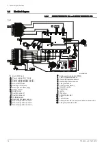
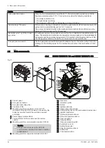
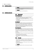
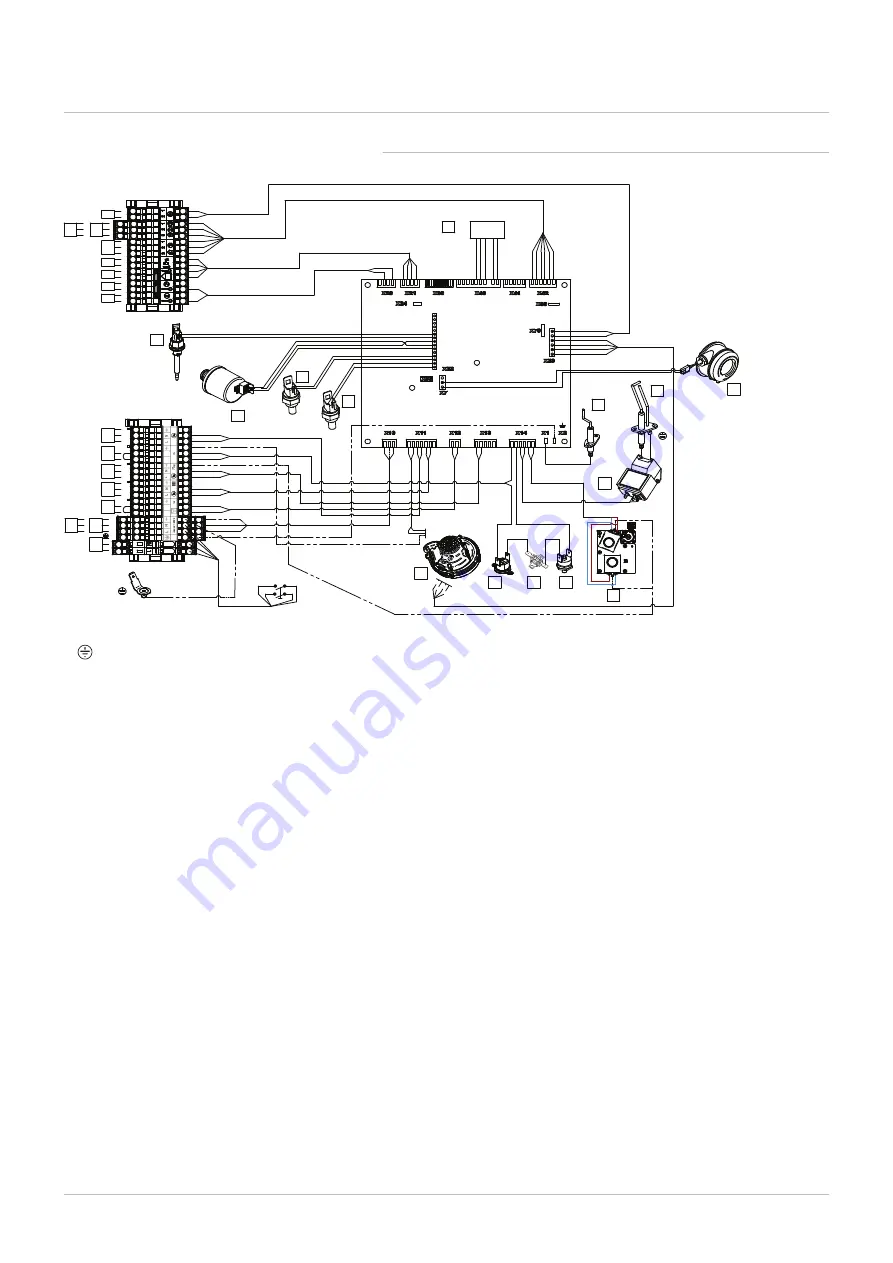
Electrical diagram
3.4.1
SIRIUS THREE FS 130 and SIRIUS THREE FS 150
Fig.4
MW
-5
0
0
0
7
1
8
-2
3
4
1A
2A
1
1
2
2
L
N
1
2
3
4
BL
BR
BL
BR
G/Y
BR
BK
BR
BK
BL
BR
WH
BK
WH
BK
WH
BK
BK
WH
BL
BL
BL
BR BR
BL
BL
G/Y
G/Y
BR
BL
BL
BR
VT
YW
BK
BR
GN
GN
GN
GN
BK
BR
BK
YW
BK
VT
GN
BR
YW
GY
BK
WH
BK
RD
VT
BR
GN
BR
VT
WH
GN
RD
BK
BR
BL
BR
BL
BR
BL
GN
BK
BR
BL
GN
BK
BR
BL
G/Y
BL
BL
G/Y
HMI
G/Y
G/Y
G/Y
G/Y
G/Y
BL
BL
BL
BL
BK
BK
RD
GN
GN
RD
PK
GR
PK
GR
RD
RD
RD
RD
A
1
2
3
4
5
6
7
8
WH
BK
BK
G/Y
BL
BR
BL
BR
BL
BR
I
J
K
L
M
P
O
N
H
G
F
E
D
C
B
9
10
12
11
BR
BL
G/Y
b
a
1
2
3
1
2
3
1
2
3
BR
13
BR
BR
T
1
T
2
S
1
S
2
V2
V1
BL
BL
BR
BR
BL
BR
14
MW-5000718-3
Earth POP rivet
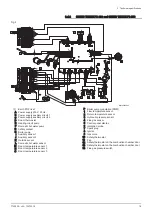
A Power supply 230 V 50 Hz
B Power supply auxiliary circuit 1
C Power supply auxiliary circuit 2
D Room thermostat
E Heating circuit pump
F Domestic hot water pump
G Safety contact
H Boiler pump
I Auxiliary sensor 1
J Auxiliary sensor 2
K Outside sensor
L Domestic hot water sensor
M Room temperature sensor 1
N Room temperature sensor 2
O Room temperature sensor 3
P Boiler pump modulation (PWM)
1 Flow temperature sensor
2 Return temperature sensor
3 Hydraulic pressure sensor
4 Flue gas sensor
5 Control panel display
6 Ionisation probe
7 Spark plug
8 Igniter
9 Gas valve
10 Safety thermostat
11 Fan
12 Thermal fuse
13 Safety thermostat on the combustion chamber door
14 Flue gas pressure switch
3 Technical specifications
18
7702639 - v03 - 10072018


