Important
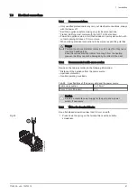
Relay the pumps if the current exceeds 1 A max per output.
6.3.3
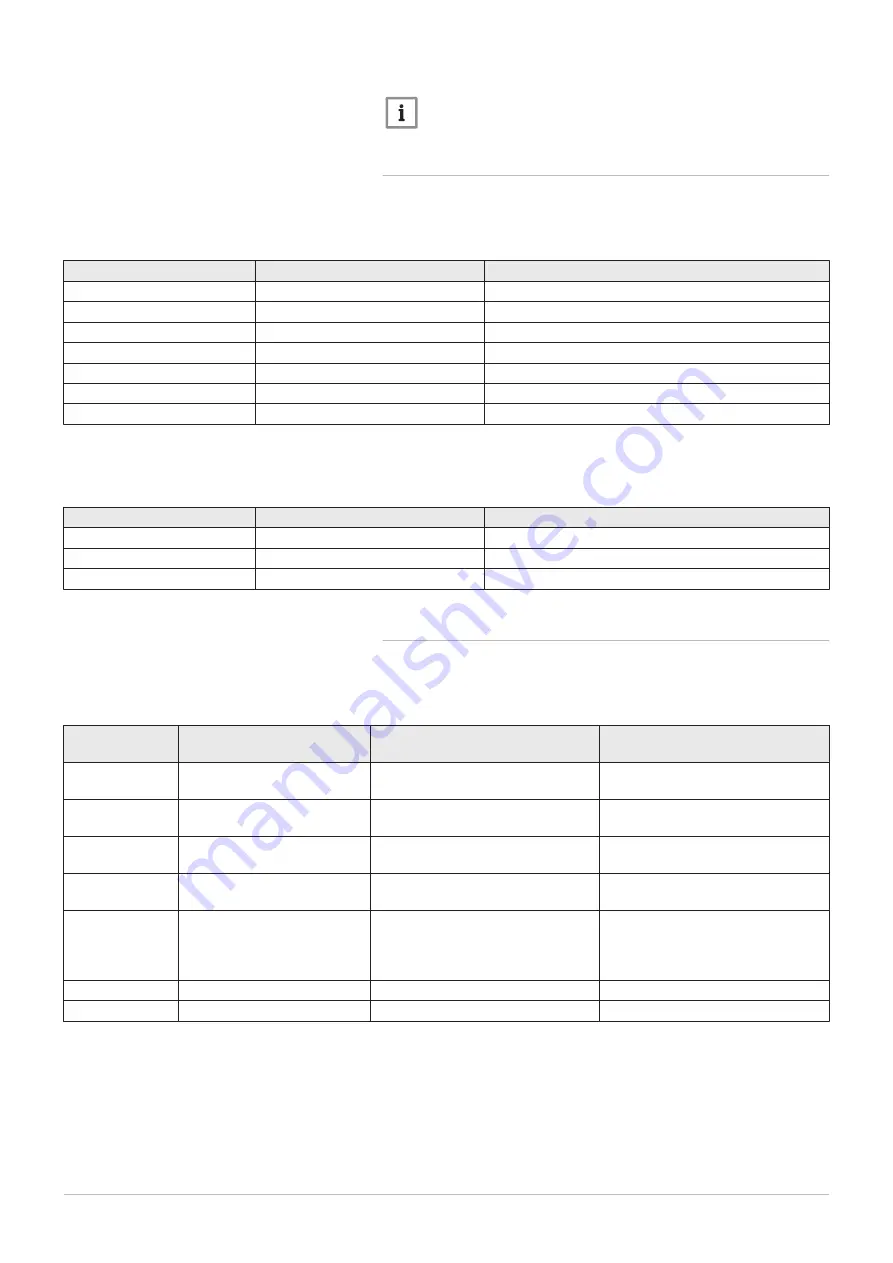
Configuration for 1 master boiler and 1 slave boiler
1. Go to the installer parameters on boiler 1 (master boiler).
2. Set the following parameters on boiler 1:
Tab.16 Settings on boiler 1 (master boiler)
Parameter number
Parameter
Adjustment required
5710
Temps / mode CH1
On
5715
Temps / mode CH2
On
5731
Sensor input BX2
Common flow sensor B10
5932
Sensor input BX3
Cascade return sensor B70
6020
Function extension module 1
Temps / mode CH2
6600
Device address
1
6640
Clock mode
Master
3. Go to the installer parameters on boiler 2 (slave boiler).
4. Set the following parameters on boiler 2:
Tab.17 Settings on boiler 2 (slave boiler)
Parameter number
Parameter
Adjustment required
5710
Temps / mode CH1
Off
6600
Device address
2
6640
Clock mode
Slave without remote setting
6.3.4
Configuration for a master boiler and slave boilers
1. Access the installer parameters of the master boiler.
2. Set the following parameters on the master boiler:
Tab.18 Configuration of the master boiler in a cascade
Parameter num
ber
Parameter
Adjustment required
Description
5977
Function input H5
None
Deactivation of the thermostat on
terminal block M1 (1–2)
6030
Relay output QX21 module 1
(three-way valve circuit)
heating pump CH1 Q2
Check on the pump on heating cir
cuit 1
6040
Sensor input BX21 module 1
Common flow sensor B10
Check on the cascade flow tempera
ture
6041
Sensor input BX22 module 1
Cascade return sensor B70
Check on the cascade return tem
perature
6200
Save sensors
Yes
Saving any modifications made.
The setting will revert automatically
to No immediately after the adjust
ment.
6630
Cascade master
Always
Identification master boiler
6640
Clock mode
Autonomously
Cascade master boiler clock setting
3. Access the installer parameters for the slave boiler(s):
6 Connecting diagrams and configuration
52
7702639 - v03 - 10072018


