23
7704679.01 (3-08/18)
10.1 BASIC CONTROL PANEL SETTINGS
INITIAL IGNITION CONFIGURATION PROCEDURE
When igniting the boiler for the first time, perform the following procedure (the text is written in
ENGLISH
until the user is requested
to set his/her language as illustrated in sequence A-B-C of the figure indicated below):
•
B
for
5 seconds;
•
the display shows a percentage value from 1 to 100. Data synchronisation takes a few minutes to complete;
•
set the language, date and time.
C
B
A
11. FILLING THE SYSTEM
The pressure displayed on the pressure gauge has to be between
1
-
1.5
bar, with the system cold. If it is lower, turn the system
filling tap installed by the fitter.
IMPORTANT: open the tap very slowly in order to vent the air.
The boiler is fitted with a hydraulic pressure switch which prevents the boiler from working if there is no water.
If pressure drops occur frequently (monthy basis), have the system checked by the Authorised technical service agent.
12. SYSTEM AIR EXTRACTION FUNCTION
This function is used to facilitate the elimination of the air inside the heating circuit when the boiler is first installed or after
maintenance when the water is drained from the primary circuit and re-filled.
The electronic board will activate a pump on/off cycle lasting 10 minutes. The function will automatically stop at the end of the
cycle.
To manually interrupt the function, repeat the procedure described above. When the function is disabled, “
off
” is shown on
the display.
During this phase it is recommended to keep the pressure in the system at a value between 1 and 1.5 bar.
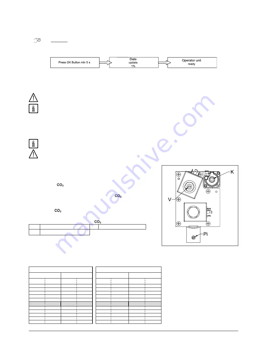
13. GAS VALVE COMMISSIONING
To commission the gas valve, enable the commission function as described in
section "SPECIAL FUNCTIONS" and carry out the following operations:
1) Calibrating MAXIMUM heat output.
Check that the
/O
2
measured on the flue duct, with the boiler operating
at maximum heat capacity, matches that indicated in table 1C. If it does not,
remove the threaded cap on the gas valve and turn the adjustment screw (
V
).
Turn the screw clockwise to decrease the level of
and anti-clockwise to
increase it.
2) Calibrating REDUCED heat output
Check that the
/O
2
measured on the flue duct, with the boiler operating at
minimum heat capacity, matches that indicated in table 1C. If it does not, remove
the threaded cap on the gas valve and turn the adjustment screw (
K
). Turn the
screw clockwise to increase the level of
and anticlockwise to decrease it.
V
Gas flow adjustment screw
Pi
Gas supply pressure tap
K
OFFSET adjustment screw
For each CO
2
/O
2
value found at the maximum thermal capacity, there is a range
of CO
2
/O
2
values at the minimum thermal capacity shown in the same line of
the table.
The nominal calibration values of the gas valve for each type of gas used are shown in bold.
The CO
2
/O
2
values are with the cover closed.
The maximum permitted CO value must be lower than 250 ppm.
TABLE 1C
G20 (Natural Gas)
G31 (Propane Gas)
CO
2
(%)
O
2
(%)
CO
2
(%)
O
2
(%)
P max
P min
P max
P min
P max
P min
P max
P min
9,7
8,8÷9,2
3,6
4,5÷5,2
10,5
10÷10,4
4,9
5,1÷5,7
9,6
8,7÷9,1
3,8
4,7÷5,4
10,4
9,9÷10,3
5,1
5,2÷5,8
9,5
8,6÷9
3,9
4,8÷5,6
10,3
9,8÷10,2
5,2
5,4÷6
9,4
8,5÷8,9
4,1
5÷5,7
10,2
9,7÷10,1
5,4
5,5÷6,1
9,3
8,4÷8,8
4,3
5,2÷5,9
10,1
9,6÷10
5,5
5,7÷6,3
9,2
8,3÷8,7
4,5
5,4÷6,1
10
9,5÷9,9
5,7
5,8÷6,4
9,1
8,2÷8,6
4,7
5,6÷6,3
9,9
9,4÷9,8
5,8
6÷6,6
9
8,1÷8,5
4,8
5,7÷6,5
9,8
9,3÷9,7
6,0
6,1÷6,7
8,9
8÷8,4
5
5,9÷6,6
9,7
9,2÷9,6
6,1
6,3÷6,9
8,8
7,9÷8,3
5,2
6,1÷6,8
9,6
9,1÷9,5
6,3
6,4÷7,1
8,7
7,8÷8,2
5,4
6,3÷7
9,5
9÷9,4
6,4
6,6÷7,2
7704153
Summary of Contents for Sirius Three WH-130
Page 1: ...May 2018 Sirius three WH 130 150 kW ...
Page 10: ...7704679 01 3 08 18 10 583 892 600 G 1 1 2 G 1 1 2 G 1 198 100 100 100 102 CR_0775 95 223 24 ...
Page 20: ...7704679 01 3 08 18 20 WEATHER COMPENSATION CURVE GRAPHS QAC34 ...
Page 35: ...35 7704679 01 3 08 18 29 DIAGRAMS AGU 2 550 CR_0349 CR_0349 AVS 75 bis ...
Page 36: ...7704679 01 3 08 18 36 CG_2482 SAFETY THERMOSTAT Tmax 50 C free contact ...
Page 37: ...37 7704679 01 3 08 18 MODIFIED PARAMETERS Nr VALUE NOTE ...
Page 38: ...7704679 01 3 08 18 38 ...
Page 39: ...39 7704679 01 3 08 18 ...


