34
intelligently applied technology
© Baxi Heating UK Limited 2005
9. Servicing
•
For reasons of safety and economy the boiler should
be serviced annually by a competent person.
•
Any 'O' rings, seals or gaskets disturbed during
servicing or replacement of parts must be
visually inspected and replaced if worn or
damaged.
•
Important: Always test for gas soundness after
servicing or replacement of gas carrying
components and carry out functional checks of
controls.
•
Ensure you are using the correct Baxi Potterton
approved spare part when replacing any items as
incorrect or sub standard parts could affect the
operation of the boiler.
•
Some seals on this boiler are special ‘wet’ type
designed for use with condensing boilers.
9.1 Servicing Procedure
1. With the outer case correctly fitted, fire the boiler and
check that the flames visible through the sight glass
are blue and stable. Yellow flame and excessive
lifting indicate poor combustion.
2. Turn the temperature control knob to ( ) position and
check that the burner shuts off. Allow the boiler to
cool and isolate the gas and electricity supplies.
The boiler cannot be isolated at the user
interface. Isolate the electricity supply at the
mains supply point.
Warning: The 70 and 80 models are fitted with a
325Vdc fan. Ensure the mains supply is isolated.
3. Pull the door panel down and remove the two
screws. Carefully slide the bottom cover out and
away from the boiler.
4. Remove the three screws and carefully lift the outer
case away from the boiler.
5. Remove the combustion chamber cover - See 9.9.
6. Visually check for debris/damage and clean or
replace if necessary the following.
a. Combustion Chamber Insulation - replace if
required, see 9.12.
b. Fan - remove as shown in 9.9.
Examine the fan impeller and carefully clean if
necessary. Check the condition of the sensing
tubes at the Fan and Air Pressure Switch.
c. Burner - remove if required, see 9.10.
Brush the burner top and check that the flame
ports are clear. Any blockage may be removed
with a fine wire brush. Turn the burner upside
down and tap gently to remove any debris
(Protect the electrodes).
d. Electrodes - remove if required, see 9.10.
If the electrodes require cleaning wipe the surface
using a solvent.
e. Injector - remove if required, see 9.11.
Omit this operation if the gas rate is correct,
otherwise clean by blowing through. Do NOT
clear the injector with a pin or wire.
f. Condensate trap - remove if required, see 9.13.
Place a vessel underneath to catch the
condensate then remove the trap drain plug. Take
care as the condensate could be hot. Clear out
any debris then re-prime the trap, see 4.6.
g. Primary heat exchanger - remove flue hood,
see 9.9.
Place a sheet of paper under the heat exchanger
then using a flat blade tool (Part No. 907736),
scrape the flueway fin surfaces in a downward
movement. This will ensure that most of the
deposits will be collected on the paper.
h. Secondary heat exchanger - remove the hood
and sump as shown in 9.15 and clean as
required.
j. Check the condition of all electrical cables and
connectors.
k. On re-assembly ensure that the outer white case
is correctly fitted and that the sealing strip fitted to
the door is forming a tight seal with the boiler
casing.
7. Inspect the flue terminal for blockage and integrity,
rectify if necessary.
8. Inspect the condensate disposal system for damage,
rectify if necessary.
9. Carry out a functional test of the controls and check
the gas rate.
10.Check the dilution of the system inhibitor and top up
as required. Failure to check and correct inhibitor
concentration may damage the heat exchanger.
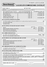
11.Complete the relevant Service Interval Record
section of the ‘Benchmark’ Commissioning Checklist
at the rear of this publication.


