Installation - Page 16
U
L
0
0
1
0
8
B
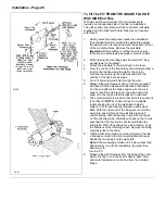
Rubber
Gasket
Inner Wall
Seal
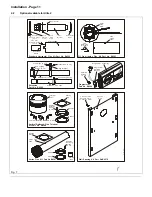
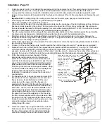
Take the Clamping
Plate & Sealing
Ring of the rear
flue outlet & fit the
side blanking plate
over the rear flue
hole. Slide the
gasket & plate
over the air tube
& secure to the
boiler chassis
with 4 screws
Fitted side blanking plate
to rear flue outlet
Outer
Wall
Plate
Mark,
drill,
plug &
secure
with 4
screws
Outer
Sealing Plate
Fit the
white
side
panel
before
fitting
the side
flue
Flue
Terminal
Fig. 19
U
L
0
0
0
2
2
A
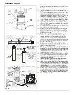
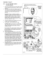
Flue
Hood
Fan & Diverter
Assembly
Right hand
Flue Outlet
Left hand
Flue Outlet
Connect flue tube sleeve to fan & slide
the whole assembly into position
Connect flue tube sleeve
to fan & slide the whole
assembly into position
Flue
Sampling
Point
Fan
Fig 20
11. Remove the cover plate from the white case side and
attach the panel to the boiler.
12. Locate the outer wall plate and rubber gasket onto the
die cast flue terminal.
13. From the outside, insert the flue through the hole in the
wall.
From the inside slide the inner wall seal over the flue
assembly.
14. Ensure that the terminal is flush with the outside wall
and that the rubber gasket is in the wall liner (sealing off
the wall liner from the outside).
15. Position the outer sealing plate, over the flue terminal,
mark the four mounting holes on the outside wall and
remove.
Note:
Cover the terminal before drilling to prevent debris
entering the terminal.
16. Drill and plug the holes to accept No. 8 x 1"
woodscrews, remove the covering from the terminal, re-
position the outer sealing plate and secure to the wall.
17. Slide the sealing ring and clamping plate over the flue
and push up to the boiler chassis. Secure using the four
screws previously removed. See Fig 19.
18. Ensure that the 'O' ring is in position on the fan outlet,
then fit the flue tube sleeve, over the fan outlet and
push it fully home.
19. Place the fan assembly on top of the flue hood with the
outlet facing to the side and connect the flue together.
Reconnect the two fan motor leads (polarity not
important) and the air pressure switch tube.
20. With the fan assembly clipped on at the back of the flue
hood.Secure the front of the fan assembly to the flue
hood with the two screws previously removed.
21. Check that the flue tube sleeve is fully connected to the
fan assembly & flue.
22. Remove the four screws securing the transit plate to the
bottom of the boiler, discard the plate and screws.
23. Remove the screw and unhook the base plate - DO
NOT discard these items.
24.
Proceed to Section 2.10.
Summary of Contents for Ultra 2
Page 6: ...Installation Requirements Page 6 Fig 1 ...
Page 7: ...Installation Requirements Page 7 Fig 2 ...
Page 9: ...Installation Requirements Page 9 ...
Page 37: ...Routine Maintenance Page 37 ...
Page 51: ...7 Wiring Diagrams Page 51 ...
Page 52: ...Wiring Diagrams Page 52 Ultra 2Dv ...
Page 53: ...Wiring Diagrams Page 53 Ultra 2 ...
Page 54: ...54 Fault Finding Part No 405 0522 8 Fault Finding Guide Page 54 ...
Page 55: ...Part No 405 0522 Fault Finding 55 Fault Finding Guide Page 55 ...
Page 56: ...56 Fault Finding Part No 405 0522 Fault Finding Guide Page 56 ...
Page 57: ...Part No 405 0522 Fault Finding 57 Fault Finding Guide Page 57 ...

