Installation - Page 28
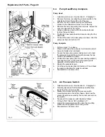
Fig. 34
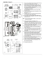
21. Remove the screw and unhook the base plate - DO
NOT discard these items.
2.10
Connect the Power Supply Cable
1.
Remove the screw securing the control box to the
thermostat mounting bracket. Swing the control box out.
2.
Two cable clamps are provided on the back of the
control box, use one just for the mains supply and the
other for any other external wiring. Slacken the
necessary cable clamp screws. Feed the power supply
cable up and over the back of the chassis, through the
uppermost clamp and into the terminal connection.
Connect the wires, brown to L and blue to N and
green/yellow to earth ().
Note:
When connecting the power supply cable, ensure
that the length of the earth wire is such, that if the
power supply cable pulls out of the cable clamp the live
and neutral wires become taut before the earth wire.
3.
Any external control wiring should be routed up and
over the back of the chassis, through the lower cable
clamp and connect to the terminal connection.
4.
Take up excess slack in the power supply cable
between the terminal block and the cable clamp, then
tighten the cable clamp screws. Repeat for any wires
through the other cable clamp.
Note:
If the optional internal programmer is to be fitted,
do so now - See Section 2.11 overleaf.
5.
Sufficient slack is available to the cable clamps to alllow
pivotel movement.
6.
Secure the control box to the thermostat bracket using
the screw previously removed.
Ensure enough cable slack is allocated to allow the
Control Box door to open and close.
7.
Carry out preliminary electrical system checks i.e. Earth
Continuity, Short Circuit, Polarity and Resistance to
Earth.
Do not switch on the electricity supply at this stage.
Summary of Contents for Ultra 2
Page 6: ...Installation Requirements Page 6 Fig 1 ...
Page 7: ...Installation Requirements Page 7 Fig 2 ...
Page 9: ...Installation Requirements Page 9 ...
Page 37: ...Routine Maintenance Page 37 ...
Page 51: ...7 Wiring Diagrams Page 51 ...
Page 52: ...Wiring Diagrams Page 52 Ultra 2Dv ...
Page 53: ...Wiring Diagrams Page 53 Ultra 2 ...
Page 54: ...54 Fault Finding Part No 405 0522 8 Fault Finding Guide Page 54 ...
Page 55: ...Part No 405 0522 Fault Finding 55 Fault Finding Guide Page 55 ...
Page 56: ...56 Fault Finding Part No 405 0522 Fault Finding Guide Page 56 ...
Page 57: ...Part No 405 0522 Fault Finding 57 Fault Finding Guide Page 57 ...

