Installation - Page 29
U
L
0
0
0
3
1
B
Terminal
Connector
(10 way)
Rear Of
Control Box
N
N
L
L
2
2
CH
HW
off
HW
CH
on
ON
Remove Link When
Connecting Controls
Cable Clamp (Use For
Mains Cable Only)
G
e
n
e
ra
l
F
u
n
c
ti
o
n
In
Hot
Live
Neutral
Cold
Sensomatic - PRT 2
TL
N
H
General Function
Load Neutral In
Honeywell - T6160B
1
2
3
Room
Thermostat
Cylinder
Thermostat
Programmer
Link 'L' to 'CH' and 'HW' if not
already linked inside programmer
Cable Clamp
(Use For All
Other Cables -
Not Mains)
S
e
n
s
o
m
a
ti
c
-
P
T
T
2
TL
C
N
L
H
H
o
n
e
y
w
e
ll
-
L
6
4
1
A
n
o
t
u
s
e
d
2
C
1
MAINS
(Fuse at
3 amp, min
0.5mm cable)
2
M
On
On
Off
HW
CH
L
N
Off
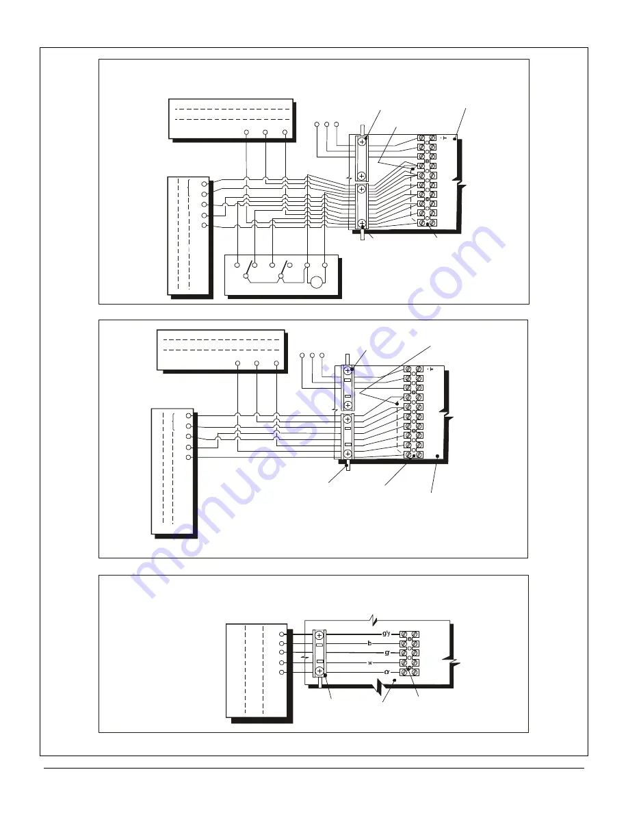
Wiring Diagrams: With External Programmer Fitted
(2 Channel Programmer) With Room & Cylinder Thermostats
Cable Clamp
(Use For Mains
Cable Only)
G
e
n
e
ra
l
F
u
n
c
ti
o
n
In
Hot
Live
Neutral
Cold
S
e
n
s
o
m
a
ti
c
-
P
T
T
2
TL
C
N
L
H
Cylinder
Thermostat
Cable Clamp
(Use For All
Other Cables -
Not Mains)
H
o
n
e
y
w
e
ll
-
L
6
4
1
A
n
o
t
u
s
e
d
2
C
1
MAINS
(Fuse at 3 amp,
min 0.5mm cable)
2
U
L
0
0
0
2
5
B
Terminal
Connector
(10 way)
Rear Of
Control Box
N
N
L
L
2
2
CH
HW
off
HW
CH
on
ON
Remove Link
When Connecting
Controls
Sensomatic - PRT 2
TL
N
H
General Function
Load Neutral In
Honeywell - T6160B
1
2
3
Room
Thermostat
Wiring Diagrams: With Internal Programmer
Fitted With Room & Cylinder Thermostats
U
L
0
0
0
9
6
B
External Diverter
Valve Connector
(5 way)
External Mid Position
Diverter Valve (If Required)
Note: This
connection
is ONLY
necessary
on non D.V.
models-
(on D.V.
models the
valve is
already in
the appliance
and connected
directly into
the P.C.B.)
Rear Of
Control Box
Use Lower
Cable Clip
Orange
White
Grey
Blue
Green &
Yellow
H
o
n
e
y
w
e
ll
V
4
0
7
3
A
Orange
White
Grey
Blue
Not
Used
S
c
a
n
g
lo
M
S
V
Orange
Brown
Grey
Blue
Not
Used
S
e
n
s
o
m
a
ti
c
P
M
V
3
For non- D.V. Models (connections for an external D.V.)
Fig. 35
Summary of Contents for Ultra 2
Page 6: ...Installation Requirements Page 6 Fig 1 ...
Page 7: ...Installation Requirements Page 7 Fig 2 ...
Page 9: ...Installation Requirements Page 9 ...
Page 37: ...Routine Maintenance Page 37 ...
Page 51: ...7 Wiring Diagrams Page 51 ...
Page 52: ...Wiring Diagrams Page 52 Ultra 2Dv ...
Page 53: ...Wiring Diagrams Page 53 Ultra 2 ...
Page 54: ...54 Fault Finding Part No 405 0522 8 Fault Finding Guide Page 54 ...
Page 55: ...Part No 405 0522 Fault Finding 55 Fault Finding Guide Page 55 ...
Page 56: ...56 Fault Finding Part No 405 0522 Fault Finding Guide Page 56 ...
Page 57: ...Part No 405 0522 Fault Finding 57 Fault Finding Guide Page 57 ...


