Installation - Page 31
2.13
Connect the Water System
& Vent the Boiler
1.
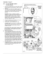
Ensure that the plastic plugs are removed from the pipe
ends and attach the isolation valves. Check the valves
are open.
2.
Install the pressure relief valve discharge pipe (min.
15mm dia.) and connect to the pressure relief outlet
using a 15mm compression fitting. This will enable the
connection to be undone if the boiler has to be
removed.
Important:
The pipe run should be as short as
possible, run continuously downwards and discharge
outside the building and over a drain. It must not
discharge above an entrance, window, any type of
public access point, any point where it would be
hazardous to occupants or cause damage to external
electrical components or wiring.
3.
Screw the pressure gauge connection into the water
manifold, leave the facia hanging down.
4.
Fill the system, ensure that all valves are open.
Dv Models Only:
The manual lever on the left hand
side of the diverter valve, must be moved from 'AUTO'
to 'MID' (manual override) when filling, venting or
draining the system.
Thoroughly flush the system through. A radiator type air
vent is positioned on the left hand side (at the front) of
the heat exchanger (on 80 models a second vent is
positioned at the rear).
5.
Refill and vent the system.
6.
The pump bearings and shaft rely on system water to
provide lubrication. It is important therefore to ensure
that the bearings have been properly vented and
that
the
pump is not run dry
otherwise damage may occur
to the bearings. Unscrew the pump manual restart
knob, and withdraw it to engage in the motor shaft.
Rotate the knob and check that the motor shaft rotates
freely. Apply a sideways pressure to the knob until a
small amount of water becomes visible. The pump is
now vented. After use, the manual restart knob should
be screwed back into its original position, finger tight.
Take care not to allow any water to drip onto the control
box or other electrics.
7.
Pressurise the system to 1.5 bar and check for leaks,
rectifying where necessary. Reset the system pressure
to 0.8 bar and set the red adjustable pointer on the
pressure gauge to 0.8 bar.
Fig. 38
Summary of Contents for Ultra 2
Page 6: ...Installation Requirements Page 6 Fig 1 ...
Page 7: ...Installation Requirements Page 7 Fig 2 ...
Page 9: ...Installation Requirements Page 9 ...
Page 37: ...Routine Maintenance Page 37 ...
Page 51: ...7 Wiring Diagrams Page 51 ...
Page 52: ...Wiring Diagrams Page 52 Ultra 2Dv ...
Page 53: ...Wiring Diagrams Page 53 Ultra 2 ...
Page 54: ...54 Fault Finding Part No 405 0522 8 Fault Finding Guide Page 54 ...
Page 55: ...Part No 405 0522 Fault Finding 55 Fault Finding Guide Page 55 ...
Page 56: ...56 Fault Finding Part No 405 0522 Fault Finding Guide Page 56 ...
Page 57: ...Part No 405 0522 Fault Finding 57 Fault Finding Guide Page 57 ...

