3. Commissioning - Page 32
U
L
0
0
0
4
6
B
C
O
M
PA
C
T
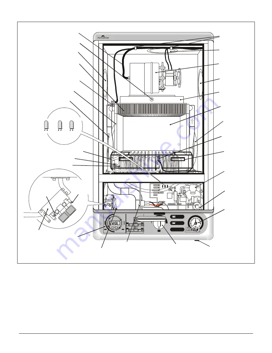
Fan & Diverter
Assembly
Flue Sampling Point
L.H. Flue Outlet
Flexible Tube Fan
Overheat Thermostat
(R.H. Side On 60
& 80 Models)
Heat Exchanger
Insulation
Thermostat
Phial
Burner Injector
Main Burner
Gas Valve Outlet Pipe
Programmer
(Optional)
Main Burner Pressure Adjusting Screw
Combustion
Chamber
Expansion
Vessel
Flue Hood
R.H. Flue
Outlet
Cable Clips
Vertical
Flue Outlet
Pilot
Assembly
Ignition
Board
Heat
Shield
Pump
Pressure
Gauge
Thermostat
Knob
Test Switch
Reset
Button
0
12
1
2
3
4
5
6
7
8
9
10
11
12
1
1
1
2
3
4
5
6
7
8
9
10
11
Off
Twice
Once
On
HW
ADV
CH
ADV
PM
AM
F l a m e
Lockout
5
6
2
b a r
1
4
Switch off electricity
before removing this
cover
- Ther
Inlet
Pressure
Test Point
Gas Valve
Burner
Pressure
Test Point
Ignition
Board
Indicator
Lights
S
w
it
c
h
e
d
L
iv
e
P
e
r
m
a
n
e
n
t
L
iv
e
P
o
la
r
it
y
R
e
v
e
r
s
e
d
Fig. 39
3.1
Commission the Boiler
1.
Prepare the boiler.
a.
A test switch is provided at the left hand side of the control box which will allow the boiler to operate during
commissioning without the programmer or external controls connected. Push the thermostat knob onto the spindle.
2.
Test for gas soundness and purge the supply.
a.
With the boiler gas cock closed (the cock is closed when the operating spindle is turned fully anti-clockwise),
pressure test the gas supply and inlet pipework connection to the boiler gas cock for soundness in accordance with
BS6891.
b.
Remove the gas inlet pressure test point screw. Ensure the gas supply is on and open the boiler gas cock to purge
in accordance with BS6891. Replace the test point screw and test for gas soundness around the screw.
Summary of Contents for Ultra 2
Page 6: ...Installation Requirements Page 6 Fig 1 ...
Page 7: ...Installation Requirements Page 7 Fig 2 ...
Page 9: ...Installation Requirements Page 9 ...
Page 37: ...Routine Maintenance Page 37 ...
Page 51: ...7 Wiring Diagrams Page 51 ...
Page 52: ...Wiring Diagrams Page 52 Ultra 2Dv ...
Page 53: ...Wiring Diagrams Page 53 Ultra 2 ...
Page 54: ...54 Fault Finding Part No 405 0522 8 Fault Finding Guide Page 54 ...
Page 55: ...Part No 405 0522 Fault Finding 55 Fault Finding Guide Page 55 ...
Page 56: ...56 Fault Finding Part No 405 0522 Fault Finding Guide Page 56 ...
Page 57: ...Part No 405 0522 Fault Finding 57 Fault Finding Guide Page 57 ...


