background image

Part No. 405/0522

Fault Finding 55

Fault Finding Guide - Page 55

Summary of Contents for Ultra 2

Page 1: ...ccordance with the above regulations Failure to install appliances correctly could lead to prosecution The polythene bags used for packaging are a potential hazard to babies and young children and MUST BE DISPOSED OF IMMEDIATELY Installation must be in accordance with the Installation Service Instructions and the rules in force LEAVE THESE INSTRUCTIONS WITH THE USER FOR USE ON FUTURE CALLS For Use...

Page 2: ...Pressure Switch 40 6 6 Diverter Valve Head Ultra 2 Dv Models 41 6 7 Pressure Gauge 41 6 8 Pressure Relief Valve 42 6 9 By Pass Valve 42 6 10 Ignition Circuit Board 43 6 11 Re Set Switch 43 6 12 Potterton Internal Programmer If Fitted 43 6 13 Test Switch 44 6 14 Overheat Cut Off Device 44 6 15 Spark Electrode Electrode Lead 45 6 16 Main Burner 46 Pilot Burner 46 Pilot Injector 46 Main Burner Inject...

Page 3: ...ature 82ºC Design water temperature rise 10ºC Height 800 mm Width 450 mm Depth 370 mm Clearance Top 50 mm 150 mm if Vertex Vertical flue kit is to be fitted required Bottom 150 mm for Front 500 mm servicing Sides 10 mm Flue terminal size 100 mm dia x 65 mm deep Water connections Compression fittings See Fig 2 Gas connection Rc bottom left hand side Mid position zone valve Dv Only Myson 22 mm Gas R...

Page 4: ...e Installer and Service Engineer Under the Consumer Protection Act 1987 and Section 6 of the Health and Safety at Work Act 1974 we are required to provide information on substances hazardous to health Small quantities of adhesives and sealants used in the product are cured and present no known hazards The following substances are also present Insulation and Seals Material Ceramic Fibre Alumino Sil...

Page 5: ...is given in BS5440 1 1990 sub clauses 3 3 and 4 2 5 If the boiler is to be installed in a timber framed building it should be fitted in accordance with the British Gas publication Guide for Gas Installation in Timber Framed Housing reference DM2 If in doubt advice must be sought from the local region of British Gas or from Potterton Myson The boiler may be installed in any room although particular...

Page 6: ...Installation Requirements Page 6 Fig 1 ...

Page 7: ...Installation Requirements Page 7 Fig 2 ...

Page 8: ... connection at the water manifold as the drain point for the boiler Fit one or more draining taps BS2879 to enable the water system to be fully drained A factory set by pass is built into the boiler and MUST NOT be adjusted The pressure relief valve MUST NOT be used to drain the boiler 1 9 Sealed System Requirements 1 The installation must comply with the requirements of BS6798 and BS5449 Maximum ...

Page 9: ...Installation Requirements Page 9 ...

Page 10: ...carefully unclipping the two neons as you pull the facia away Note Unplug programmer if fitted from back of the control box 5 Pull the bottom of the white front case forward to release the bottom ball studs continue pulling until the top studs release then lift slightly and pull away from the boiler 6 Remove the two white side panels 2 screws each side 7 Remove the combustion chamber cover 4 screw...

Page 11: ...6 off Extension Flue Tube V ertex Flue T ube Gasket Gasket Terminal Securing Brackets Screws Adaptor Adaptor Spacing Plate 5 Screws Wall Mounting Plate To Spacing Plate Adaptor Securing Screws 4 off Sealing Tape Adaptor Securing Screws 4 off Terminal Cowl Sealing Plate Sealing Plate Extension Air T ube Centralizing Spring Fixing Bracket Woodscrews 2 off Flue Tube Sleeve Wall Spacing Kit Part No B4...

Page 12: ... is available from Tower Flue Components Ltd at Vale Rise Tonbridge Kent TN9 1TB Tel 01732 351555 The guard must be securely fitted to the wall and centrally located over the flue terminal Refer to the manufacturers instructions 2 3 Fit the Optional Wall Spacing Kit The wall spacing kit allows the boiler to be spaced 40 mm from the wall providing sufficient room for all pipework to be run behind t...

Page 13: ...ugh the wall if possible use a 127mm 5 core drill 3 Measure the wall thickness and cut the wall liner to the same length Insert the wall liner into the wall ensure the seam is to the top and that the tabs are horizontal no screws are required as the wall liner will be held in place by the wall mounting plate Make good the wall if required 4 Attach the wall mounting plate to the wall Ensure it is l...

Page 14: ...ng to prevent debris entering the terminal 14 Drill and plug the holes to accept No 8 x 1 woodscrews remove the covering from the terminal re position the outer sealing plate and secure to the wall 15 Slide the sealing ring and clamping plate over the flue and push up to the boiler chassis Secure using the four screws previously removed See Fig 13 16 Ensure that the O ring is in position on the fa...

Page 15: ...ove the four screws and clamping plate sealing ring from the rear of the boiler chassis Remove the blanking plate from the side of the chassis fit to the rear flue opening Lift the boiler into position over the wall plate The two V shaped cut outs in the top mounting bracket locate behind the two prongs on the wall plate Note If the measurement taken in paragraph 8 below is less than 600mm carry o...

Page 16: ... off the wall liner from the outside 15 Position the outer sealing plate over the flue terminal mark the four mounting holes on the outside wall and remove Note Cover the terminal before drilling to prevent debris entering the terminal 16 Drill and plug the holes to accept No 8 x 1 woodscrews remove the covering from the terminal re position the outer sealing plate and secure to the wall 17 Slide ...

Page 17: ...e flue terminal assembly using the three screws supplied with the extension Seal the joint with the tape supplied with the extension Bend the end of the support bracket s so it joins a wall or ceiling member secure with two screws plugs provided 6 Return to the section you were at before this one and carry on with the installation UL00121B F or flues with extensions measure from the boiler chassis...

Page 18: ...o suit a 3 in Twin Wall B vent flue system from Rite Vent Armstrong Industrial Estate Washington Tyne Wear NE37 1LH Tel 0191 416 1150 Storm Collar Ref 156 Adjustable Flashing Ref 151 Minimum Flue length dimension A 1 2m Length of Vertical Flue dimension A Standard flue 750mm One flue extension 1750mm Two flue extensions 2750mm Three flue extensions 3250mm Terminal Position Min Distance A Directly ...

Page 19: ...section of the roof and flue this will ensure adequate clearances for the safe operation of the boiler From dimension A determine the number of flue extensions required if any and cut the flue tubes to the required length Ensure that the tubes are cut square Remove all burrs 10 Fit the flue terminal cowl over the end of the flue terminal die casting and secure the three support brackets to the bot...

Page 20: ...ring and clamping plate from the rear of the chassis remove the sealing plate and four fixing screws from the top of the chassis and fit this to the rear of the chassis 17 Remove the four screws securing the fan to the flue diverter rotate the fan so that the outlet is facing upwards and secure it to the diverter with the four screws previously removed Remove the 3 screws securing the fan motor to...

Page 21: ...g ensure there are no water pipes gas pipes or electric cables 3 Drill and plug the wall to accept 2 long woodscrews not supplied 4 Attach the wall plate to the wall Ensure it is level A line is marked at the top of the mounting plate which indicates the centre line of the Vertex Flue Continue this line vertically upwards to the ceiling This line must not be closer than 75 mm to any ceiling joist ...

Page 22: ...d clamping plate from the rear of the chassis remove the sealing plate and four fixing screws from the top of the chassis and fit this to the rear of the chassis 13 Lift the boiler into position over the wall plate The two V shaped cut outs in the top mounting bracket locate behind the two prongs on the wall plate Take care not to damage the flue 14 Insert a woodscrew not supplied into the bottom ...

Page 23: ...1 22551 Using their 4 Twin Wall IL Gas Vent flue system with special draught hood connector Part No 55504 3 Three No 10 x 25 mm long screws are supplied with the kit to centralise the connector into the Vertex Flue socket This connector must be adequately sealed to the Vertex Flue socket 4 Complete the boiler installation as described in the boiler Installation instructions 5 Instruct the User not...

Page 24: ...ness and cut the liner supplied with this kit to the finished wall thickness LESS 2mm Cut the end without the hooks and ensure the cut is square Insert the wall liner into the wall ensure the seam is to the top and that the tabs are vertical no screws are required as the wall liner will be held in place by the wall mounting plate Make good the wall if required 4 The outer wall plate is made so tha...

Page 25: ...g the remaining two screws Carefully bend the brackets over the edge of the outer flue tube to retain it in position to stop the flue being pushed into the boiler Refit the flue hood 11 Insert a woodscrew not supplied into the bottom fixing hole to secure the boiler to the wall 12 Ensure that the O ring is in position on the fan outlet then fit the flue tube sleeve over the fan outlet and push it ...

Page 26: ...t to the finished wall thickness LESS 2mm Cut the end without the hooks and ensure the cut is square Insert the wall liner into the wall ensure the seam is to the top and that the tabs are horizontal 7 The outer wall plate is made so that when it is opened it is not flat Do NOT try to bend it flat Tie a suitable length of string to one of the wall plate chains to support it if it is inadvertently ...

Page 27: ...ews Carefully bend the brackets over the edge of the outer flue tube to retain it in position to stop the flue being pushed into the boiler 15 Insert a woodscrew not supplied into the bottom fixing hole to secure the boiler to the wall Slide the inner wall seal up to the wall so it covers over the wall liner 16 Ensure that the O ring is in position on the fan outlet then fit the flue tube sleeve o...

Page 28: ...e pulls out of the cable clamp the live and neutral wires become taut before the earth wire 3 Any external control wiring should be routed up and over the back of the chassis through the lower cable clamp and connect to the terminal connection 4 Take up excess slack in the power supply cable between the terminal block and the cable clamp then tighten the cable clamp screws Repeat for any wires thr...

Page 29: ...Cold Sensomatic PTT 2 TL C N L H Cylinder Thermostat Cable Clamp Use For All Other Cables Not Mains Honeywell L641A not used 2 C 1 MAINS Fuse at 3 amp min 0 5mm cable 2 UL00025B Terminal Connector 10 way Rear Of Control Box N N L L 2 2 CH HW off HW CH on ON Remove Link When Connecting Controls Sensomatic PRT 2 TL N H General Function Load Neutral In Honeywell T6160B 1 2 3 Room Thermostat Wiring Di...

Page 30: ...facia hanging down for the time being 2 12 Connect the Gas Supply Connect the gas supply using a suitable adaptor to the gas cock The pipe diameter required will depend on the boiler model and the pipe length from the gas meter 15mm dia pipe will be adequate for the following lengths Boiler Models 30 15m 40 9m 50 7 5m 60 5m 80 3m These lengths must be reduced by 0 5m for each elbow and tee fitted ...

Page 31: ...e moved from AUTO to MID manual override when filling venting or draining the system Thoroughly flush the system through A radiator type air vent is positioned on the left hand side at the front of the heat exchanger on 80 models a second vent is positioned at the rear 5 Refill and vent the system 6 The pump bearings and shaft rely on system water to provide lubrication It is important therefore t...

Page 32: ...nlet Pressure T est Point Gas Valve Burner Pressure T est Point Ignition Board Indicator Lights Switched Live Permanent Live Polarity Reversed Fig 39 3 1 Commission the Boiler 1 Prepare the boiler a A test switch is provided at the left hand side of the control box which will allow the boiler to operate during commissioning without the programmer or external controls connected Push the thermostat ...

Page 33: ...ed fully anti clockwise and the test switch is set to Override b Turn the thermostat knob fully clockwise The unit will go through the automatic ignition sequence and the pilot will light A second or so after the pilot is lit the main gas solenoid will open and the main burner will light c Test the main burner manifold connection at the gas valve for gas soundness using a suitable leak detecting f...

Page 34: ...ide s and secure to the front of the boiler using the screws previously removed 3 Hook the white front case on at the top of the boiler position so the ball studs align with the holes in the white case sides and push firmly to engage them 4 Locate the facia assembly onto the front of the boiler and secure to the white case sides using the two countersunk screws previously removed 3 5 Light the Boi...

Page 35: ... and installation should be examined and rectified as necessary 1 Check that the system pressure is 0 8 bar cold 2 Run the boiler and check the operation of its controls and ensure that it responds to any switches and programmer 3 Check the installation of the flue terminal and ensure it is not obstructed Note A flue sampling point has been provided on this boiler It is accessible after removal of...

Page 36: ... assembly 10 Undo the tubing nut and disconnect the pilot supply from the pilot assembly Carefully remove and retain the pilot injector 11 Remove the two screws securing the right hand end of the burner to the chassis Slide the burner to the right to remove it from the main injector and withdraw the burner 5 3 Cleaning the Boiler 1 Brush the heat exchanger from above and below using a suitable bru...

Page 37: ...Routine Maintenance Page 37 ...

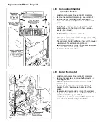
Page 38: ...1 Replacement of any component requires the removal of the facia assembly and white front case as follows a Pull down the control cover flap to expose the facia Pull off the thermostat control knob Remove the 2 screws securing the facia to the side panels and remove the facia control cover carefully unclipping the two neons as you pull the facia away Note The facia can only be completely removed f...

Page 39: ...pen the gas service cock and test the union and inlet manifold to gas valve connection for gas soundness 12 Referring to the Commissioning Instructions light the boiler test the pilot supply and burner manifold connections at the gas valve for gas soundness Adjust the burner pressure setting to give the correct rating as shown by the arrow on the data label then adjust the 1st step pressure to tha...

Page 40: ...n the two pump unions taking care not to twist the pipework Support the pump fully release the two unions and withdraw the pump 4 Position the new pump use two new sealing washers ensuring the arrow on the side of the pump points upwards and fully tighten the unions 5 Rewire the pump as shown 6 Vent the pump as described in Section 2 13 and check the pump connections for water soundness 7 Re assem...

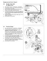
Page 41: ... in reverse order 6 7 Pressure Gauge 1 Gain General Access See Section 6 1 Paragraph 1 2 Drain the boiler by removing the pressure gauge connection from the water manifold Note When the boiler is drained filled or vented the manual lever on the left hand side of the diverter valve must be moved to the MID manual override position Return it to its original position after the system has been filled ...

Page 42: ...ubricant 6 Re assemble in reverse order 6 9 By Pass Valve 1 Gain General Access See Section 6 1 Paragraph 1 2 Drain the system by removing the pressure gauge connection from the water manifold Note When the system is drained filled or vented the manual lever on the left hand side of the diverter valve must be moved to the MID manual override position Return it to its original position after the sy...

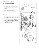
Page 43: ... the air pressure switch Section 6 5 will allow the reset button to be slid out to the left 2 Disconnect the harness from the circuit board 3 Compress the clips on the side and pull the reset button through the chassis 4 Re assemble in reverse order 6 12 Potterton Internal Ultra 2 Programmer If Fitted 1 Gain General Access See Section 6 1 Paragraph 1 2 Note how it fits and unplug the programmer wi...

Page 44: ... out of the control box 4 Fit the new switch as shown with the spade connectors to the bottom 5 Re assemble in reverse order 6 14 Overheat Cut Off Device 1 Gain General Access See Section 6 1 complete 2 Disconnect the overheat thermostat leads 3 Remove the two screws securing the overheat thermostat to the heat exchanger 4 Ensure that the mounting plate is clean smear some heat conductive grease o...

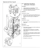
Page 45: ...Connect the electrode lead to the spark electrode 6 Re assemble in reverse order Electrode lead 1 Gain General Access See Section 6 1 complete 2 Disconnect the electrode lead from the spark electrode 3 Disconnect the electrode lead from the ignition circuit board 4 Carefully pull the electrode lead out through the white silicone grommets in the right side of the chassis 5 Carefully feed the new le...

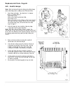
Page 46: ...ove it from the main injector and withdraw the burner Pilot Burner Follow steps 1 to 4 plus 5 Remove the two screws securing the pilot burner to the main burner Main Injector Follow steps 1 to 4 plus 6 Unscrew the main injector from the burner manifold and remove the sealing washer On re assembly of the main injector use a suitable sealing compound on the threads and also use a new sealing washer ...

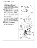
Page 47: ...over the fan outlet and push it fully home Secure the new fan to the diverter with the four screws previously removed 5 Place the fan assembly on top of the flue hood with the outlet facing towards the flue Re connect the two violet leads polarity not important to the fan motor and the air pressure tube to the fan 6 With the fan assembly resting on the flue hood engage the flue tube sleeve on the ...

Page 48: ...a few mm then pulled forwards out of its bottom locating channel Note For some models it may be necessary to remove the burner first refer to Section 6 16 5 Re assemble in reverse order 6 19 Boiler Thermostat 1 Gain General Access See Section 6 1 complete 2 Remove the two screws securing the thermostat to its mounting bracket 3 Withdraw the boiler thermostat and disconnect the electrical plugs 4 R...

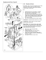
Page 49: ...d the manual lever on the left hand side of the diverter valve must be moved to the MID manual override position Return it to its original position after the system has been filled and vented 3 Remove the two screws securing the overheat thermostat to the heat exchanger 4 Undo the two tubing nuts at the bottom of the heat exchanger and remove it from the boiler lift it up slightly to disengage the...

Page 50: ...system has been filled and vented 3 Disconnect the flexible pipe from the water manifold Side Removal Remove the white case side two screws Top Removal If the flue exits out the rear it will need disconnecting to allow access Boiler off wall Close all service cocks water and gas Section 2 12 2 13 isolate electricity supply Section 2 10 remove fan assembly Section 6 17 Disconnect the water and gas ...

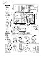
Page 51: ...7 Wiring Diagrams Page 51 ...

Page 52: ...Wiring Diagrams Page 52 Ultra 2Dv ...

Page 53: ...Wiring Diagrams Page 53 Ultra 2 ...

Page 54: ...54 Fault Finding Part No 405 0522 8 Fault Finding Guide Page 54 ...

Page 55: ...Part No 405 0522 Fault Finding 55 Fault Finding Guide Page 55 ...

Page 56: ...56 Fault Finding Part No 405 0522 Fault Finding Guide Page 56 ...

Page 57: ...Part No 405 0522 Fault Finding 57 Fault Finding Guide Page 57 ...

Page 58: ...9 Short List Of Spare Parts Page 58 ...

Page 59: ...rner 12 Blade 80 Models Only 1 929064 16 398 379 Burner Injector Bray 23 800 30 Models Only 1 929002 17 398 380 Burner Injector Bray 23 1100 40 Models Only 1 929003 18 398 475 Burner Injector Bray 23 1350 50 Models Only 1 929004 19 389 586 Burner Injector Bray 23 1600 60 Models Only 1 405 0623 20 398 381 Burner Injector Bray 23 2400 80 Models Only 1 929006 21 323 468 Washer Injector 1 929230 22 28...

Reviews: