background image

12

OPERATION

TO OPERATE ON HILLS

CAUTION:  Do not drive up or down hills
with slopes greater than 15° and do not
drive across any slope.

Choose the slowest speed  before starting up or down
hills.

Avoid stopping or changing speed on hills.

If slowing is necessary, move throttle control lever to
slower position.

If stopping is absolutely necessary, push clutch/brake
pedal quickly to brake position and engage parking
brake.

Move motion control lever to neutral (N) position.

IMPORTANT:

THE  MOTION CONTROL LEVER DOES

NOT RETURN TO NEUTRAL (N) POSITION WHEN THE
CLUTCH/BRAKE PEDAL IS DEPRESSED.

To restart movement, slowly release parking brake and
clutch/brake pedal.

Slowly move motion control lever to slowest setting.

Make all turns slowly.

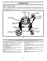
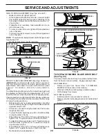
TO OPERATE MOWER (See Fig. 8)

Your tractor  is equipped with an operator presence sensing
switch.  Any attempt by the operator to leave the seat with
the engine running and the attachment clutch engaged will
shut off the engine.

Select desired height of cut.

Start mower blades by engaging attachment clutch
control.

TO STOP MOWER BLADES - disengage attachment
clutch control.

CAUTION:  Do not operate the mower
without either the entire grass catcher,
on mowers so equipped, or the deflector
shield in place.

ATTACHMENT
CLUTCH LEVER
"DISENGAGED"
POSITION

ATTACHMENT
LIFT LEVER
HIGH POSITION

"ENGAGED" POSITION

LOW
POSITION

FIG. 8

FIG. 9

TOWING CARTS AND OTHER ATTACHMENTS

Tow only the attachments that are recommended by and
comply with specifications of the manufacturer of your
tractor. Use common sense when towing. Too heavy of a
load, while on a slope, is dangerous. Tires can lose traction
with the ground and cause you to lose control of your tractor.

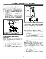
FIG. 7

3/8-16
LOCKNUT

3/8 WASHER

GAUGE WHEEL

SHOULDER
BOLT

GUAGE WHEEL
MOUNTING
BRACKET

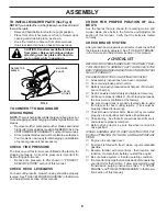
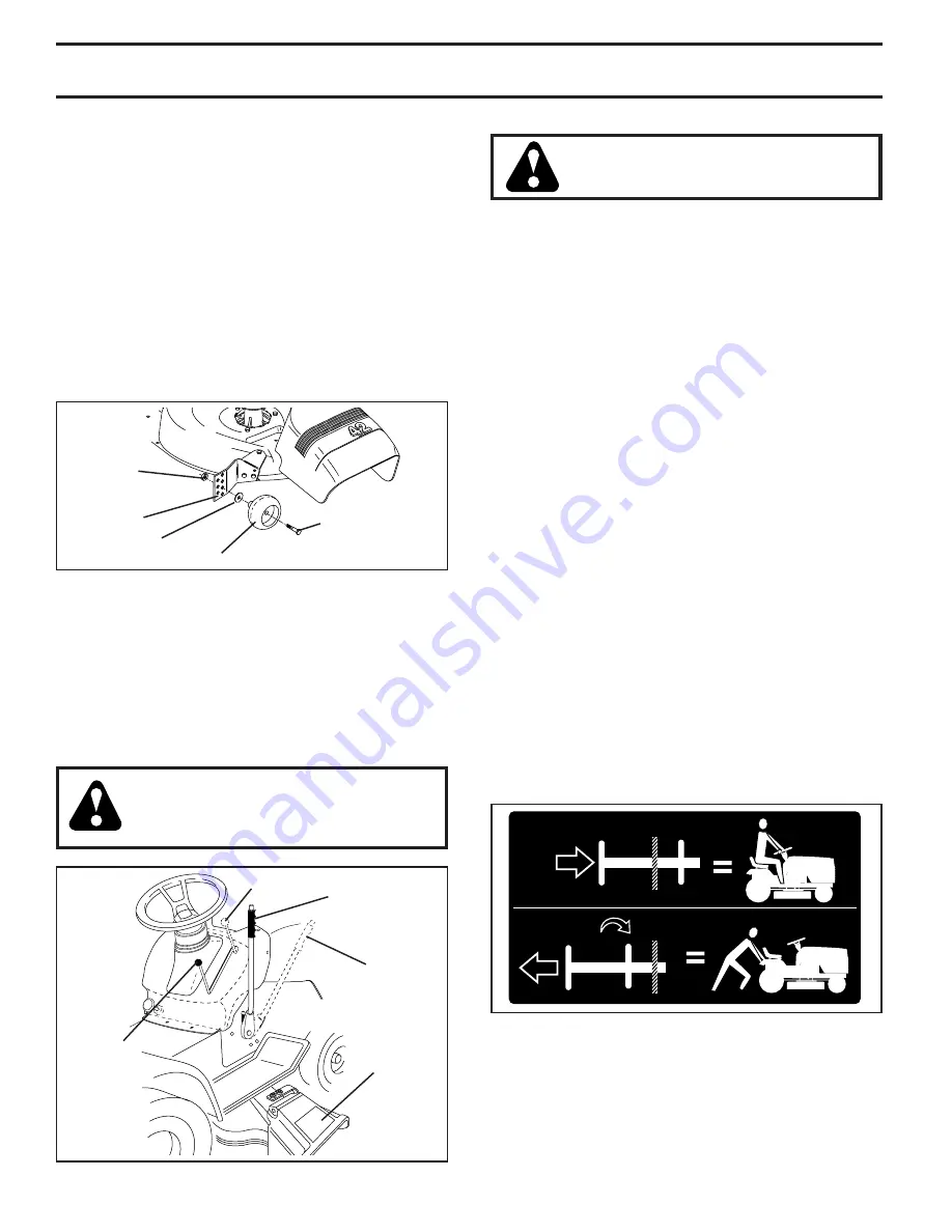
TO ADJUST GAUGE WHEELS (See Fig. 7)

Gauge wheels  are properly adjusted when they are slightly
off the ground when mower is at the desired cutting height in
operating position. Gauge wheels then keep the deck in
proper position to help prevent scalping in most terrain
conditions.

Adjust gauge wheels with tractor on a flat level surface.

Adjust mower to desired cutting height (See “TO AD-
JUST MOWER CUTTING HEIGHT” in the Operation
section of this manual).

With mower in desired height of cut position, gauge
wheels should be assembled so they are slightly off the
ground. Install gauge wheel in appropriate hole with
shoulder bolt, 3/8 washer, and 3/8-16 locknut and tighten
securely.

Repeat for opposite side installing gauge wheel in same
adjustment hole.

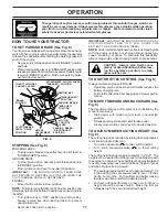
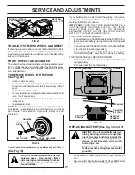
TO TRANSPORT (See Figs. 5 and 9)

When pushing or towing your tractor, be sure to disengage
transmission by placing freewheel control in freewheeling
position.  Free wheel control is located at the rear drawbar of
tractor.

Raise attachment lift to highest position with attach-
ment lift control.

Pull freewheel control out and down into the slot and
release so it is held in the disengaged position.

Do not  push or tow tractor at more than two (2) MPH.

To reengage transmission, reverse above procedure.

NOTE:  To protect hood from damage when transporting
your tractor on a truck or a trailer, be sure hood is closed and
secured to tractor.  Use an appropriate means of tying hood
to tractor (rope, cord, etc.).

DEFLECTOR
SHIELD

Summary of Contents for 173304

Page 1: ...AYS WEAR EYE PROTECTION DURING OPERATION WARNING Read this Owner s Manual and follow all Warnings and Safety Instructions Failure to do so can result in serious injury IMPORTANT MANUAL Do Not Throw Away 173304 Rev 1 1 17 00 JH MH Printed in U S A TM ...

Page 2: ...for Ride On Mowers IMPORTANT THIS CUTTING MACHINE IS CAPABLE OF AMPUTATING HANDS AND FEET AND THROWING OBJECTS FAILURE TO OBSERVE THE FOLLOWING SAFETY INSTRUCTIONS COULD RESULT IN SERIOUS INJURY OR DEATH SAFETYRULES DONOT Do not turn on slopes unless necessary and then turn slowly and gradually downhill if possible Do not mow near drop offs ditches or embankments Themowercouldsuddenlyturnoverifawh...

Page 3: ...he area Before and when backing look behind and down for small children Mow up and down slopes 15 Max not across Remove obstacles such as rocks tree limbs etc Watch for holes ruts or bumps Uneven terrain could overturn the machine Tall grass can hide obstacles Use slow speed Choose a low gear so that you will not have to stop or shift while on the slope Avoid starting or stopping on a slope If tir...

Page 4: ...le you to assemble and maintain your tractor properly Always observe the SAFETY RULES WARNING This tractor is equipped with an internal com bustion engine and should not be used on or near any unimproved forest covered brush covered or grass cov ered land unless the engine s exhaust system is equipped with a spark arrester meeting applicable local or state laws if any If a spark arrester is used i...

Page 5: ...x Bolt 5 16 18 x 1 1 4 1 Hex Bolt 3 8 16 x 1 1 Lock washer 3 8 Steering Wheel Insert Steering Sleeve Steering Wheel 1 Knob 1 Washer 17 32 x 1 3 16 x 12 Gauge Seat 1 Shoulder Bolt 5 16 18 2 Mulch Blades 2 Keys Slope Sheet Steering Extension Shaft Steering Adapter ...

Page 6: ...ntingholesinextensionandlowershaftsandinstall 5 16 hex bolt and locknut Tighten securely Place tabs of steering boot over tab slots in dash and push down to secure INSTALL STEERING WHEEL Position front wheels of the tractor so they are pointing straightforward Removesteeringwheeladapterfromsteeringwheeland slide adapter onto steering shaft extension Positionsteeringwheelsocrossbarsarehorizontal le...

Page 7: ... of controls WARNING Beforestarting read understandandfollow all instructions in the Operation section of this manual Be sure tractor is in a well ventilated area Be sure the area in front of tractor is clear of other people and objects Be sure all the above assembly steps have been completed Check engine oil level and fill fuel tank with gasoline Place freewheel control in transmission engaged po...

Page 8: ...ated at the factory for shipping purposes Correct tire pressure is important for best cutting performance Reduce tire pressure to PSI shown in PRODUCT SPECIFICATIONS section of this manual CHECK DECK LEVELNESS For best cutting results mower housing should be properly leveled See TOLEVELMOWERHOUSING intheService and Adjustments section of this manual CHECK FOR PROPER POSITION OF ALL BELTS See the f...

Page 9: ...ARD FAST SLOW ENGINE ON ENGINE OFF OIL PRESSURE LIGHTS ON FUEL CHOKE MOWER HEIGHT PARKING BRAKE LOCKED UNLOCKED REVERSE NEUTRAL HIGH LOW ATTACHMENT CLUTCH ENGAGED MOWER LIFT DANGER KEEP HANDS AND FEET AWAY FREE WHEEL Automatic Models only OVER TEMP LIGHT PARKING BRAKE IGNITION ATTACHMENT CLUTCH DISENGAGED P KEEP AREA CLEAR SLOPE HAZARDS 15 15 15 SEE SAFETY RULES SECTION ...

Page 10: ...and brak ing the tractor and starting the engine PARKINGBRAKE Locksclutch brakepedalintothebrake position FREEWHEEL CONTROL Disengages transmission for pushing or slowly towing the tractor with the engine off MOTION CONTROL LEVER Selects the speed and direction of tractor ATTACHMENT LIFT LEVER Used to raise lower and adjustthemowerdeckorotherattachmentsmountedtoyour tractor LIFT LEVER PLUNGER Used...

Page 11: ... Failure to move throttle control to slow position and allowingenginetoidlebeforestoppingmaycauseengineto backfire Turn ignition key to OFF position and remove key Always remove key when leaving tractor to prevent unauthorizeduse Never use choke to stop engine PARKING BRAKE ENGAGED POSITION MOTION CONTROL LEVER THROTTLE CHOKE CONTROL LEVER IGNITION KEY DISENGAGED POSITION ATTACHMENT CLUTCH LEVER E...

Page 12: ...ractor Use common sense when towing Too heavy of a load while on a slope is dangerous Tires can lose traction withthegroundandcauseyoutolosecontrolofyourtractor FIG 7 3 8 16 LOCKNUT 3 8 WASHER GAUGE WHEEL SHOULDER BOLT GUAGE WHEEL MOUNTING BRACKET TO ADJUST GAUGE WHEELS See Fig 7 Gauge wheels are properly adjusted when they are slightly off the ground when mower is at the desired cutting height in...

Page 13: ... Fig 15 The engine in your tractor has been shipped from the factory already filled with summer weight oil Check engine oil with tractor on level ground Remove oil fill cap dipstick and wipe clean reinsert the dipstick and screw cap tight wait for a few seconds remove and read oil level If necessary add oil until FULL mark on dipstick is reached Do not overfill For cold weather operation you shoul...

Page 14: ...veways etc After one or two rounds mow in the opposite direction making left hand turns until finished See Fig 10 If grass is extremely tall it should be mowed twice to reduce load and possible fire hazard from dried clip pings Make first cut relatively high the second to the desiredheight Do not mow grass when it is wet Wet grass will plug mowerandleaveundesirableclumps Allowgrasstodry beforemowi...

Page 15: ...y 7 Tighten front axle pivot bolt to 35 ft lbs maximum Do not overtighten 1 12 3 2 5 5 6 7 GENERAL RECOMMENDATIONS The warranty on this tractor does not cover items that have beensubjectedtooperatorabuseornegligence Toreceive full value from the warranty operator must maintain tractor as instructed in this manual Some adjustments will need to be made periodically to properly maintain your tractor ...

Page 16: ...arallel with the ground If blade is balanced it should remain in a horizontal position If either end of the blade moves downward sharpen the heavy end until the blade is balanced TRACTOR Always observe safety rules when performing any mainte nance BRAKE OPERATION Iftractorrequiresmorethansix 6 feetstoppingdistanceat high speed in highest gear then brake must be adjusted See TOADJUSTBRAKE intheServ...

Page 17: ...elts are not adjustable Replace belts if they begin to slip from wear TRANSAXLE COOLING The transmission fan and cooling fins should be kept clean to assure proper cooling Do not attempt to clean fan or transmission while engine is runningorwhilethetransmissionishot Topreventpossible damage to seals do not use high pressure water or steam to clean transaxle Inspect cooling fan to be sure fan blade...

Page 18: ...azard and or damage SPARK PLUGS Replace spark plugs at the beginning of each mowing season or after every 100 hours of operation whichever occurs first Spark plug type and gap setting are shown in PRODUCT SPECIFICATIONS section of this manual IN LINE FUEL FILTER See Fig 18 The fuel filter should be replaced once each season If fuel filter becomes clogged obstructing fuel flow to carburetor replace...

Page 19: ...WER See Fig 19 Raise attachment lift lever to its highest position Slide mower under tractor with discharge guard to right side of tractor Lower lift lever to its lowest position Install mower in reverse order of removal instructions SUSPENSION ARMS RETAINER SPRINGS BOTH SIDES RETAINER SPRING ANTI SWAY BAR FRONT LINK COLLAR ENGINE PULLEY CLUTCH SPRING SMALL RETAINER SPRING SQUARE HOLE HOUSING GUID...

Page 20: ...ssary adjustments check that both front links are equal in length Both links should be approximately10 3 8 If links are not equal in length adjust one link to same length as other link Tolowerfrontofmowerloosennut E onbothfrontlinks an equal number of turns Whendistance D is1 8 to1 2 loweratfrontthanrear tighten nuts F against trunnion on both front links To raise front of mower loosen nut F from ...

Page 21: ...ut pulley and over cooling fan blades Pull belt toward front of tractor and remove downward from around engine pulley Install new belt by reversing above procedure FIG 26 ENGINE PULLEY CLUTCHING IDLER STATIONARY IDLER TRANSMISSION INPUT PULLEY TRANSAXLE MOTION CONTROL LEVER NEUTRAL ADJUSTMENT See Fig 27 The motion control lever has been preset at the factory and adjustment should not be necessary ...

Page 22: ...from bat teries Alwaysweareyeprotectionwhen aroundbatteries FIG 28 RETAINING RING WASHERS SQUARE KEY REAR WHEEL ONLY AXLE COVER ADJUSTMENT BOLT FIG 27 NEUTRAL LOCK GATE MOTION CONTROL LEVER If your battery is too weak to start the engine it should be recharged If jumper cables are used for emergency starting follow this procedure IMPORTANT YOUR TRACTOR IS EQUIPPED WITH A 12 VOLT NEGATIVE GROUNDED ...

Page 23: ...PEED OVERSPEEDING THE ENGINE ABOVE THE FACTORY HIGH SPEED SETTING CAN BE DANGEROUS IF YOU THINK THE ENGINE GOVERNED HIGH SPEED NEEDS ADJUSTING CONTACT YOUR NEAREST AUTHORIZED SERVICE CENTER DEPARTMENT WHICH HAS PROPER EQUIPMENT AND EXPERIENCE TO MAKE ANY NECESSARY ADJUSTMENTS ENGINE TO ADJUST THROTTLE CONTROL CABLE See Fig 33 The throttle control has been preset at the factory and adjustment shoul...

Page 24: ...NG IN ESSENTIAL FUEL SYSTEM PARTS SUCH AS CARBURETOR FUEL FILTER FUEL HOSE OR TANK DURING STORAGE ALSO EXPERIENCE INDICATES THAT ALCOHOL BLENDED FUELS CALLED GASOHOL OR USING ETHANOL OR METHANOL CAN ATTRACT MOISTURE WHICH LEADS TO SEPARATION AND FORMATION OF ACIDS DURING STORAGE ACIDIC GAS CAN DAMAGE THE FUEL SYSTEM OF AN ENGINE WHILE IN STORAGE Drain the fuel tank Start the engine and let it run ...

Page 25: ...heck replace ignition switch 8 Faulty solenoid or starter 8 Check replace solenoid or starter 9 Faulty operator presence switch es 9 Contact an authorized service center department Engine clicks but will not 1 Weak or dead battery 1 Recharge or replace battery start 2 Corroded battery terminals 2 Clean battery terminals 3 Loose or damaged wiring 3 Check all wiring 4 Faulty solenoid or starter 4 Ch...

Page 26: ...eplace sharpen blade Tighten blade bolt 7 Buildup of grass leaves and trash under mower 7 Clean underside of mower housing 8 Mower drive belt worn 8 Replace mower drive belt 9 Blades improperly installed 9 Reinstall blades sharp edge down 10 Improper blades used 10 Replace with blades listed in this manual 11 Clogged mower deck vent holes from buildup of 11 Clean around mandrels to open vent holes...

Page 27: ...ERNATOR SYSTEM THE LIGHTS ARE NOT CONNECTED TO THE BATTERY BUT HAVE THEIR OWN ELECTRICAL SOURCE BECAUSE OF THIS THE BRIGHTNESS OF THE LIGHTS WILL CHANGE WITH ENGINE SPEED AT IDLE THE LIGHTS WILL DIM AS THE ENGINE IS SPEEDED UP THE LIGHTS WILL BECOME THEIR BRIGHTEST WIRING INSULATED CLIPS NOTE IF WIRING INSULATED CLIPS WERE REMOVED FOR SERVICING OF UNIT THEY SHOULD BE REPLACED TO PROPERLY SECURE YO...

Page 28: ...28 TRACTOR MODEL NUMBER PR17H42STA ELECTRICAL 28 29 26 24 42 43 27 27 25 41 27 27 40 33 30 8 2 1 27 D C AMPERES 45 16 16 22 21 52 ...

Page 29: ...CableBattery 25 146147 Cable Battery 6 Ga Red w 16 wire 26 166180 Fuse 15 Amp 27 73510400 Nut Keps Hex 1 4 20 Unc 28 4207J Cable Ground 6ga 12 black 29 121305X Switch Plunger Nc Gray 30 163968 Switch Ign 33 140401 Key Ign Molded Generic 40 170217 HarnessIgn 41 71110408 Bolt Fin Hex 1 4 20uncx 1 2 42 131563 CoverTerminalRed 43 145673 Solenoid 45 121433X AmmeterRectangular 52 141940 ProtectionLoop N...

Page 30: ...EL NUMBER PR17H42STA CHASSIS 58 207 20 207 23 64 208 13 208 11 1 3 2 9 208 208 5 5 207 3 3 3 142 3 3 3 142 17 29 28 12 51 57 53 52 54 55 145 37 3 37 24 26 25 26 25 3 31 24 30 35 3 26 33 10 26 34 35 18 3 38 3 206 212 ...

Page 31: ...8X428 Fender Footrest STLT Pnt 31 136619 BracketFender 33 145244X428 Footrest Pnt Lh 34 145243X428 Footrest Pnt Rh 35 72110606 Bolt Rdhd Sht Sqnk 3 8 16 x 3 4 37 17490508 Screw Thdrol 6 16 18 x 1 2 TYT 38 169834 Bracket Asm Pivot Mower Rear 51 73800400 Nut Lock Hex W Ins 1 4 20 52 19091416 Washer 9 32 x 7 8 x 16 Ga 53 144697 Bracjet Grukke Lh 54 161464 Screw Hex Wshd 8 18 x 7 8 55 144696 Bracket G...

Page 32: ... 40 53 35 55 36 42 62 35 36 22 39 34 16 1 77 77 30 52 56 64 65 51 72 63 116 70 57 96 26 25 19 24 26 26 76 78 75 74 27 26 15 37 51 51 27 51 48 151 202 49 26 47 50 51 81 156 166 165 82 168 163 14 164 21 8 10 83 159 161 198 158 162 169 150 84 16 199 16 61 71 200 73 16 61 197 95 89 69 ...

Page 33: ...12 Screw Thdrol 3 8 16 x 75 62 8883R Cover Pedal 63 140186 Pulley Engine 64 71170764 Bolt Hex 65 10040700 Washer 66 154778 Keeper Belt Engine 69 142432 Screw 70 134683 Guide Belt 71 169183 Strap Torque Lh Hydro 72 19132012 Washer 13 32 x 1 1 4 x 12 Gauge 73 169182 Strap Torque Rh Hydro 74 169496 Spacer Axle 75 121749X Washer 25 32 x 1 1 4 x 16 Gauge 76 12000001 E Ring 77 123583X Key Square 78 1217...

Page 34: ...R PR17H42STA STEERING ASSEMBLY 11 22 5 5 4 3 43 6 43 8 18 19 27 62 23 11 40 66 29 25 79 8 40 32 8 6 46 46 8 6 2 1 41 17 42 37 36 37 38 63 11 39 44 51 54 33 35 34 80 68 67 67 67 13 65 68 15 15 15 29 29 29 29 82 10 47 47 85 85 ...

Page 35: ... Washer Lock Hvy Hlcl Spr 5 16 35 73540500 Crownlock Nut 5 16 24 Unf 36 155099 Bushing Strg 37 152927 Screw 38 159946X428 Insert Cap Strg Wh 39 74760644 Washer 13 32 X 1 1 2 X 11 Ga 40 7810H Lock nut 41 159945 Adaptor Wheel Strg 42 145054X428 Boot Steering Dash 43 121749X Washer 25 32 X 1 1 4 X 16 Ga 44 153720 Extension Steering Shaft LR LT 46 121232X Cap Spindle Fr Top Blk 47 6855M FittingGrease ...

Page 36: ...11 166369 Knob Seat 12 121246X Bracket Mounting Switch 13 121248X Bushing Snap Blk Nyl 50 Id 14 72050412 Bolt Rdhd Sqnk 1 4 20x1 1 2 15 134300 Spacer Split 28x 88 16 121250X SpringCprsn 17 123976X Nut Lock 1 4 Lge Flg Gr 5 Zinc 21 171852 Bolt Shoulder 5 16 18 Unc 22 73800500 Nut Hex Lock W Ins 5 16 18 24 19171912 Washer 17 32 X 1 3 16 X 12 Ga 25 127018X Bolt Shoulder 5 16 18 X 62 KEY PART NO NO DE...

Page 37: ... 170456 Tire R T 20x10 8 Service 10 7152J Tube Rear Service Item Only 11 104757X Cap Axle Blk 1 50 X 1 00 144334 Sealant Tire 10 oz Tube 8 20 14 5 1 157032 DecalOper 2 172741 Decal Fender Auto 3 172738 Decal Hood LH 4 172739 Decal Side Panel Logo 5 170856 Decal HP Engine 6 169210 Decal By Pass Lt Hydro 8 170563 Decal Mower Warn Keep Hand Away 9 172740 DecalFenderLogo 10 157140 Decal Fender Danger ...

Page 38: ...38 TRACTOR MODEL NUMBER PR17H42STA ENGINE 2 1 OPTIONAL EQUIPMENT Spark Arrester 29 44 46 32 31 33 37 33 40 62 13 4 72 78 81 3 14 38 15 16 78 23 45 ...

Page 39: ...r Flat Scrn 31 161911 Tank Fuel Front 2 00 32 140527 Cap Asm Fuel W sym Vented 33 123487X Clamp Hose Black 37 137040 Line Fuel 20 38 Plug Oil Drain OrderFromEngineManufacturer 40 124028X Bushing Snap Nyl Blk Fuel Line 44 17670412 ScrewHexwshThdrol1 4 20x3 4 45 17000612 Screw Hexwsh Thdr 3 8 16 x 3 4 46 19091416 Washer 9 32 X 7 8 X 16 Ga 62 10040500 Washer Lock Hvy Hlcl Spr 5 16 72 71070512 Screw H...

Page 40: ... 142 149 142 35 49 50 51 54 52 53 55 56 34 1 46 44 21 22 24 25 26 27 2 28 29 23 21 21 21 18 18 20 2 48 59 19 4 3 5 6 21 40 143 36 40 37 40 159 152 151 153 154 157 158 67 153 156 155 113 117 116 118 119 114 115 112 121 114 117 119 116 115 111 118 121 113 102 102 104 103 105 106 104 105 106 103 101 90 90 91 92 93 94 93 92 95 ...

Page 41: ...Shoulder 5 16 18 UNC 53 131845 Arm Assembly Pad Brake 54 133943 Washer Hardened 55 155046X421 Arm Idler 56 122052X Spacer Retainer 59 141043 Guard TUV Idler 67 171598 KnobRound 68 144959 V Belt 42 Mower 90 74760616 Bolt Fin Hex 3 8 16 Unc x 1 91 132274 Bracket Asm Noseroller LH 92 73800600 Nut Lock Hex W Ins 3 8 16 UNC 93 19171416 Washer 17 3 x 7 8 x 6 Ga 94 132264 Roller Nose 38 42 95 132273 Brac...

Page 42: ...42 TRACTOR MODEL NUMBER PR17H42STA MOWER LIFT 36 15 20 16 1718 20 20 15 20 4 5 6 2 3 1 6 5 4 7 8 23 24 25 27 28 29 30 50 26 37 41 40 38 12 11 31 32 31 32 19 19 13 13 13 13 49 ...

Page 43: ... Unc 19 139868 Arm Suspension Rear 20 163552 RetainerSpring 23 110807X Nut Special 24 19131016 Washer 13 32 X 5 8 X 16 Ga 25 2876H Spring2 1 8 26 169484 RetainerClip 27 126971X Rod Adj Lift Zinc 7 49 Wrk Lg 28 73350600 Nut Hex Jam 3 8 16 Unc 29 138057 Knob Inf 3 8 16 Unc Blk W sym 30 150233 TrunnionInfinHeight 31 140302 Bearing Pvt Lift Spherical 32 73540600 Nut Crownlock 3 8 24 36 155097 Pointer ...

Page 44: ...44 SERVICE NOTES ...

Page 45: ...45 SERVICE NOTES ...

Page 46: ...sed for rental or commercial purposes is limited to 90 days from the date of original purchase 5 This Warranty applies only to products which have been properly assembled adjusted operated and maintained in accordance with the instructions furnished This Warranty does not apply to any product which has been subjected to alteration misuse abuse improper assembly or installation delivery damage or t...

Page 47: ...IDE ONLY RIDE UP AND DOWN HILL NOT ACROSS HILL SUGGESTED GUIDE FOR SIGHTING SLOPES FOR SAFE OPERATION Operate your Tractor up and down the face of slopes not greater than 15 never across the face Make turns gradu ally to prevent tipping or loss of control Exercise extreme caution when changing direction on slopes ...

Page 48: ...mers Brushcutters and Blowers 3 For replacement parts have available the following information a Model Number Manufacturer s I D Number b Description of part NOTE Frigidaire Home Products provides parts and service through its authorized distributors and dealers therefore all requests for parts and service should be directed to your local dealer s The philosophy of Frigidaire Home Products is to c...

Reviews: