background image

11

MAINTENANCE

GENERAL RECOMMENDATIONS

The warranty on this tiller does not cover items that  have 
been subjected to operator abuse or negligence.  To receive 
full value from the warranty, the operator must main tain tiller 
as instructed in this manual.

Some adjustments will need to be made periodically to 
properly maintain your tiller.

All adjustments in the Service and Adjustments section 
of this manual should  be checked  at  least  once each 
season.
•      Once a year you should replace the spark plug, clean 

or replace air fi lter, and check tines and belts for wear.  
A new spark plug and clean air fi lter assure proper 
air-fuel mixture and help your engine run better and 
last longer.

BEFORE EACH USE

•      Check engine oil level.
•      Check tine operation.
•      Check for loose fasteners.

LUBRICATION

Keep unit well lubricated (See “LUBRICATION CHART”). 

LUBRICATION CHART

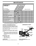
MAINTENANCE
SCHEDULE

FILL IN DATES
AS YOU COMPLETE
REGULAR SERVICE

Check Engine Oil Level

Change Engine Oil

Oil Pivot Points

Inspect Air Screen

Inspect Spark Arrester / Muffler

Clean or Replace Air Cleaner Cartridge

Clean Engine Cylinder Fins

Replace Spark Plug

BEFORE EACH USEEVERY 25 HOURS

EVERY 5 HOURS EVERY 50 HOURS

SERVICE DATES

1,2

2

1 - Change more often when operating under a heavy load or in high ambient temperatures.
2 - Service more often when operating in dirty or dusty conditions. 

EVERY SEASON

RH Gear Case Grease Fitting (1oz.)

c

SAE 30 OR 10W-30 MOTOR OIL 

d

REFER TO MAINTENANCE “ENGINE” SECTION

e

EP #1 GREASE

d

 ENGINE

c

 IDLER

  BRACKET

c

 WHEEL

   HUB

c

 LEVELING

  SHIELD
  HINGES

c

 DEPTH 

STAKE PIN

c

 THROTTLE  CONTROL

e

RH GEAR CASE 

GREASE FIT TING

Summary of Contents for 188904

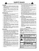
Page 1: ...R ALWAYS WEAR EYE PROTECTION DURING OPERATION 188904 11 25 03 TR Printed in U S A WARNING Read this Owner s Manual and follow all Warnings and Safety Instructions Failure to do so can result in seriou...

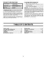
Page 2: ...to stop the unit and disengage the controls quickly Never allow children to operate the equipment Never allow adults to operate the equipment without proper instruction Keep the area of operation clea...

Page 3: ...e and should not be used on or near any unimprovedforest covered brush coveredorgrasscovered land unless the engine s exhaust system is equipped with a spark arrester meeting applicable local laws if...

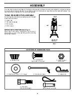
Page 4: ...been assembled at the factory with exception of those parts left unassembled for shipping purposes To ensure safe and proper operation of your tiller all parts and hardware you assemble must be tighte...

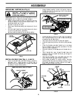
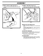
Page 5: ...is lowered into position HANDLE ASSEMBLY FIG 3 HANDLE ASSEMBLY GEARCASE NOTCH HANDLE LOCK VIEWED FROM R H SIDE OF TILLER LOOSEN HANDLE LOCK LEVER TO MOVE TIGHTEN HANDLE LOCK LEVER TO HOLD handles_34 C...

Page 6: ...lip through hole of shift rod to secure FIG 7 FIG 6 END OF CLUTCH CABLE CONTROL BAR CONTROL BAR BRACKET CONTROL BAR BRACKET CLUTCH CABLE ATTACH CLUTCH CABLE See Fig 6 Hook end of clutch cable through...

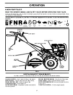
Page 7: ...SHIFT LEVER INDICATOR THROTTLE CONTROL OUTER SIDE SHIELD FIG 8 MEETS ANSI SAFETY REQUIREMENTS Our tillers conform to the safety standards of the American National Standards Institute CHOKE CONTROL Us...

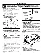
Page 8: ...easeorrocktiller forward and backward until are able to shift gears DEPTH STAKE See Fig 10 The depth stake can be raised or lowered to allow you more versatile tilling and cultivating or to more easil...

Page 9: ...cids during storage Acidic gas can damage the fuel system of an engine while in storage To avoid engine problems the fuel system should be emptied before storage of 30 days or longer Drain the gas tan...

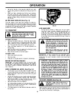
Page 10: ...end of the growing season to further condition the soil You will find tilling much easier if you leave a row un tilled between passes Then go back between tilled rows See Fig 14 There are two reasons...

Page 11: ...ine operation Check for loose fasteners LUBRICATION Keep unit well lubricated See LUBRICATION CHART LUBRICATION CHART MAINTENANCE SCHEDULE FILL IN DATES AS YOU COMPLETE REGULAR SERVICE Check Engine Oi...

Page 12: ...ossible engine damage from running low on oil Change the oil after every 25 hours of operation or at least once a year if the tiller is not used for 25 hours in one year Check the crankcase oil level...

Page 13: ...right hand side gear case grease fitting with 1 oz of EP 1 Grease CLEANING Do not clean your tiller when the engine and transmission are hot We do not recommend using pressurized water garden hose et...

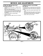
Page 14: ...oil which can damage rubber TO REMOVE WHEEL See Fig 21 Place blocks under transmission to keep tiller from tipping Remove outer side shield by removing nuts A and B Remove inner side shield by removi...

Page 15: ...GROOVE ON TOP OF IDLER PULLEY NOTE POSITION OF BELT TO GUIDES Check belt adjustment as described below Replace belt guard Reposition wheel and replace clevis pin and hairpin clip GROUND DRIVE BELT AD...

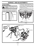
Page 16: ...o maintain the superb tilling performance of this machine the tines should be checked for sharpness wear and bending particularly the tines which are next to the transmission If the gap between the ti...

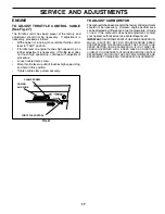
Page 17: ...hrottle lever up until it touches high speed stop and hold in this position Tighten cable clamp screw securely TO ADJUST CARBURETOR Thecarburetorhasbeenpresetatthefactoryandadjustment should not be ne...

Page 18: ...ace belts if necessary See belt re placement instructions in the Service and Adjustments section of this manual Lubricate as shown in the Maintenance section of this manual Be sure that all nuts bolts...

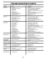
Page 19: ...d clean carburetor 6 Stale or dirty fuel 6 Empty fuel tank and refill with fresh gasoline 7 Water in fuel 7 Empty fuel tank and carburetor and refill tank with fresh gasoline 8 Clogged fuel tank 8 Rem...

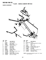
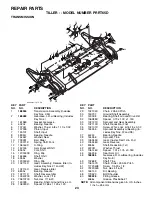
Page 20: ...NO DESCRIPTION 1 180634 Control Throttle 2 9266R Grip Handle 4 159228 Bar Assembly Control 6 180678 Panel Control 8 71191008 Screw Phd 10 24 10 8206H Grip Handle 11 4497H Clip Hairpin 12 81328 Bolt S...

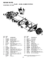
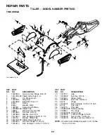
Page 21: ...X Rim 795R Tire Valve REPAIR PARTS TILLER MODEL NUMBER PRRT65D MAINFRAME LEFT SIDE KEY PART NO NO DESCRIPTION 24 126875X Rivet Drilled 25 4497H Clip Hairpin 26 165501X013 Guard Belt 27 132801 Belt V 2...

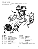
Page 22: ...t Reinforcement 6 74760528 Bolt Hex 5 16 18 x 1 3 4 7 102173X Counter Weight R H 8 10040600 Washer Lock 3 8 9 73220600 Nut Hex 3 8 16 10 74760524 Bolt Hex 5 16 18 x 1 1 2 11 4497H Clip Hairpin NOTE Al...

Page 23: ...earing Needle 23 102111X Shaft Reverse Idler 24 10040700 Washer Lock 7 16 25 73610700 Nut Hex 7 16 20 27 143009 Bearing Shaft Ground Drive L H 28 106390X Spacer 0 765 x 1 125 x 1 23 REPAIR PARTS TILLE...

Page 24: ...r Lock Hvy Helical 1 4 KEY PART NO NO DESCRIPTION KEY PART NO NO DESCRIPTION 1 73900500 Nut Lock Hex Flange 5 16 18 2 161415X428 Shield Side Outer L H 3 8393J Pin Stake Depth 4 12000035 Ring Klip 5 72...

Page 25: ...ne Inner L H 4 3146R Retainer Spring Zinc 5 132727 Assembly Hub and Plate L H 6 73610600 Nut Hex 3 8 24 7 10040600 Washer Lock 3 8 8 74610616 Bolt Hex 3 8 24 x 1 9 4460J Tine Outer R H 10 132728 Assem...

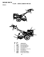
Page 26: ...2180X Decal Shift Indicator 7 162384 Decal caution 9 120076X Decal Warning Rotating Tines 11 173538 Decal Rewind 13 173698 Decal B S Tank 14 173248 Decal B S Air Cleaner 188904 Manual Owner s English...

Page 27: ...rranty does not apply to any product which has been subjected to alteration misuse abuse improper assembly or installation delivery damage or to normal wear of the product 5 Exclusions Excluded from t...

Page 28: ...immers Brushcutters and Blowers 3 For replacement parts have available the following information a Model Number Manufacturer s I D Number b Description of part NOTE Electrolux Home Products provides p...

Reviews: