background image

21

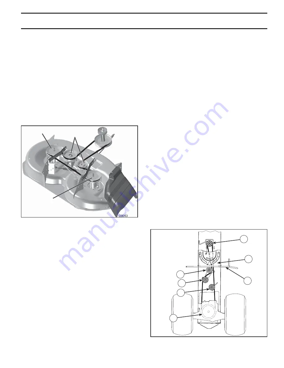
Fig. 34

TO CHECK BRAKE 

If tractor requires more than five (5) feet to stop at highest 

speed in high est gear on a level, dry concrete or paved 

surface, then brake must be serviced.
You may also check brake by:
1.  Park tractor on a level, dry concrete or paved surface, 

depress brake pedal all the way down and engage 

parking brake.

2.  Disengage transmission by placing freewheel control 

in “transmission disengaged” position. Pull freewheel 

control out and into the slot and release so it is held in 

the disengaged position.

The rear wheels must lock and skid when you try to manu-

ally push the tractor forward. If the rear wheels rotate, 

then the brake needs to be serviced. Contact a qualified 

service center.

MANDREL

PULLEY

IDLER

PUL LEYS

MANDREL

PULLEY

TO REPLACE MOWER BLADE DRIVE BELT 

(See Fig. 33)

The mower blade drive belt may be replaced without tools.  

Park the tractor on level surface.  Engage parking brake.  
BELT REMOVAL -
•  Remove mower from tractor (See “TO REMOVE 

MOW ER” in this section of manual).

•  Work belt off both mandrel pulleys and idler pulleys.
•  Pull belt away from mower. 
BELT INSTALLATION -
• 

Work belt around both mandrel pulleys and idler pulleys.

•  Make sure belt is in all pulley grooves and in side all 

belt guides.

• 

Install mower (See "To Install Mower" in this section of 

manual).

Fig. 33

TO REPLACE MOTION DRIVE BELT 

(See Fig. 34)

Park the tractor on level surface.  En gage parking brake.  

For as sis tance, there is a belt installation guide decal on 

bottom side of left footrest.
BELT REMOVAL -
• 

Remove mower (See “TO REMOVE MOWER” section 

in this manual).

NOTE:

 Observe entire motion drive belt and position of all 

belt guides and keepers.
•  Remove belt from stationary idler (A) and clutching 

idler (B).

•  Remove belt from centerspan idler (C).
• 

Pull belt slack toward rear of trac tor.  Carefully remove 

belt up wards from trans mis sion input pulley and over 

cooling fan blades (D).

•  Remove belt downward from engine pulley (E).
•  Slide belt toward rear of tractor, off the steering plate 

(F) and remove from tractor.

BELT INSTALLATION -
• 

Install new belt from tractor rear to front, over the steer-

ing plate (F) and above clutch brake pedal shaft (G).

• 

Pull belt toward front of tractor and roll belt onto engine 

pulley (E).

• 

Pull belt toward rear of tractor. Carefully work belt down 

around transmission cooling fan and onto the input 

pulley (D). Be sure belt is inside the belt keeper.

•  Install belt on centerspan idler (C).
•  Install belt through stationary idler (A) and clutch ing 

idler (B).

•  Make sure belt is in all pulley grooves and in side all 

belt guides and keep ers.

•  Install mower (See “TO INSTALL MOWER” section in 

this manual).

02952

A

B

C

D

E

F

G

SERVICE AND ADJUSTMENTS

Summary of Contents for 427159

Page 1: ... PROTECTION DURING OPERATION Visit our website www poulan pro com WARNING Read this Manual and follow all Warnings and Safety Instructions Failure to do so can result in serious injury IMPORTANT MANUAL Do Not Throw Away 427159 02 03 09 AP Printed in the U S A 03076 ...

Page 2: ...king brake stop engine and remove keys before dismounting Disengage blades when not mowing Shut off engine and wait for all parts to come to a complete stop before cleaning the machine removing the grass catcher or unclogging the discharge guard Operate machine only in daylight or good artificial light Do not operate the machine while under the influence of alcohol or drugs Watch for traffic when ...

Page 3: ...owed equipment except at the hitch point Follow the manufacturer s recommendation for weight limits for towed equipment and towing on slopes Never allow children or others in or on towed equip ment On slopes the weight of the towed equipment may cause loss of traction and loss of control Travel slowly and allow extra distance to stop V SERVICE SAFE HANDLING OF GASOLINE To avoid personal injury or ...

Page 4: ...nce and Stor age sections of this owner s manual WARNING This tractor is equipped with an internal com bustion engine and should not be used on or near any unimprovedforest covered brush coveredorgrass covered land unless the engine s exhaust system is equipped with a spark arrester meeting applicable local or state laws if any If a spark arrester is used it should be maintained in effective worki...

Page 5: ...el 1 Washer Seat 1 Seat Steering Boot Steering Extension Shaft Steering Wheel Adapter Key s Slope Sheet 1 Oil Drain Tube For Future Use 1 Hex Bolt 1 Hex Bolt 1 Lock Washer 1 Large Flat Washer Steering Wheel Insert UNASSEMBLED PARTS ...

Page 6: ...e parts and parts cartons from carton Cut along dashed lines on all four panels of carton Remove end panels and lay side panels flat Check for any additional loose parts or cartons and remove BEFORE REMOVING TRACTOR FROM SKID 03132 LOWER STEERING SHAFT STEERING BOOT EXTENSION SHAFT BOLT STEERING WHEEL INSERT ADAPTER LARGE FLAT WASHER TAB TAB SLOT LOCK WASHER TO CHECK BATTERY See Fig 1 Lift seat to...

Page 7: ...ures that are shown for replacing motion and mowerbladedrivebeltsintheServiceandAdjustmentssec tion of this manual Verify that the belts are routed correctly CHECK BRAKE SYSTEM Afteryoulearnhowtooperateyourtractor checktoseethat the brake is operating properly See TO CHECK BRAKE in the Service and Adjustments section of this manual CHECKLIST BEFORE YOU OPERATE YOUR NEW TRACTOR WE WISH TO ASSURE TH...

Page 8: ... death The safety alert symbol is used to identify safety inform ation about hazards which can result in death serious injury and or property damage DANGER indicates a hazard which if not avoided will result in death or serious injury WARNING indicates a hazard which if not avoided could result in death or serious injury CAUTION indicates a hazard which if not avoided might result in minor or mode...

Page 9: ...nform to the applicable safety standards of the American National Standards Institute Fig 5 LIGHT SWITCH Turns the headlights on and off PARKING BRAKE Locks clutch brake pedal into the brake position REVERSE OPERATION SYSTEM ROS ON POSI TION Allows operation of mower deck or other powered attachment while in reverse THROTTLE CHOKE CONTROL Used for starting and controlling engine speed FREEWHEEL CO...

Page 10: ...r to DISENGAGED position CAUTION Always stop tractor com pletely asdescribedabove beforeleav ing the operator s position to empty grass catcher etc ATTACHMENT CLUTCH LEVER ENGAGED ATTACHMENT CLUTCH LEVER DISENGAGED D F Fig 8 GROUND DRIVE To stop ground drive depress clutch brake pedal into full BRAKE position Move motion control lever to neutral position ENGINE Move throttle control between half a...

Page 11: ...JUST GAUGE WHEELS See Fig 11 Gauge wheels are properly adjusted when they are slightly offthegroundwhenmowerisatthedesiredcuttingheightin operatingposition Gaugewheelsthenkeepthedeckinprop erpositiontohelppreventscalpinginmostterrainconditions NOTE Adjustgaugewheelswithtractoronaflatlevelsurface Adjust mower to desired cutting height See TO AD JUST MOWER CUTTING HEIGHT in the Operation section of ...

Page 12: ...UTRALPOSITIONWHENTHECLUTCH BRAKE PEDAL IS DEPRESSED To restart movement slowly release parking brake and clutch brake pedal Slowly move motion control lever to slowest setting Make all turns slowly TO START ENGINE See Fig 5 When starting the engine for the first time or if the engine has run out of fuel it will take extra cranking time to move fuel from the tank to the engine Besurefreewheelcontro...

Page 13: ...osition Allow one minute for transmission to warm up This can be done during the engine warm up period Theattachmentscanalsobeusedduringtheenginewarm up period after the transmission has been warmed up NOTE If at a high altitude above 3000 feet or in cold temperatures below 32 F the carburetor fuel mixture may need to be adjusted for best engine performance See TO ADJUST CARBURETOR in the Service ...

Page 14: ...es not cover items that have beensubjectedtooperatorabuseornegligence Toreceive full value from the warranty operator must maintain tractor as instructed in this manual Some adjustments will need to be made periodically to properly maintain your tractor At least once a season check to see if you should make any of the adjustments described in the Service and Adjustments section of this manual At l...

Page 15: ...rator presence and reverse operation systems are working properly If your tractor does not function as described repair the problem immediately The engine should not start unless the brake pedal is fully depressed and the attachment clutch control is in the disengaged position CHECK OPERATOR PRESENCE SYSTEM Whentheengineisrunning anyattemptbytheoperator to leave the seat without first setting the ...

Page 16: ...in is in the locked position as shown Remove the drain tube and replace the cap onto to the bottom fitting of the drain valve Refill engine with oil through oil fill dipstick tube Pour slowly Do not overfill For approximate capacity see PRODUCTSPECIFICATIONS sectionofthismanual Use gauge on oil fill cap dipstick for checking level Be sure dipstick cap is tightened securely for accurate reading Kee...

Page 17: ...rt of its deck wash system It should be utilized after each use 1 Drive the tractor to a level clear spot on your lawn near enough to a water spigot for your garden hose to reach IMPORTANT Make certain the tractor s discharge chute is directed AWAY from your house garage parked cars etc Remove bagger chute or mulch cover if attached 2 Make sure the PTO Blade Engage is not engaged set the parking b...

Page 18: ...sion arm A from chassis and rear lift link C from rear mower bracket D remove retainer springs and washers Go to other side of mower and disconnect the suspen sion arm and rear lift link CAUTION Afterrearliftlinksarediscon nected the attachment lift lever will be springloaded Haveatightgriponliftle verwhenchangingpositionofthelever Slide mower out from under right side of tractor TO INSTALL MOWER ...

Page 19: ...e of tractor ATTACH REAR LIFT LINKS C Lift rear corner of mower and position slot in link assembly over pin D on rear mower bracket and secure with washer and retainer spring Repeat on opposite side of tractor Insert end of link E into hole in front mower bracket and secure with washer and retainer spring J Hook end of clutch cable spring Q into hole in idler arm R Push clutch cable housing guide ...

Page 20: ...mower or lower the high side Go to side of mower you wish to adjust With a 3 4 or adjustable wrench turn lift link adjust ment nut A to the left to lower the mower or to the right to raise the mower NOTE Each full turn of adjustment nut will change mower height about 3 16 Test your adjustment by mowing some uncut grass and visually checking the appearance Readjust if necessary until you are satisf...

Page 21: ...guides Install mower See To Install Mower in this section of manual Fig 33 TO REPLACE MOTION DRIVE BELT See Fig 34 Park the tractor on level surface Engage parking brake For assistance there is a belt installation guide decal on bottom side of left footrest BELT REMOVAL Remove mower See TO REMOVE MOWER section in this manual NOTE Observe entire motion drive belt and position of all belt guides and...

Page 22: ...nd of the BLACK cable D to good chassis ground away from fuel tank and battery TO REMOVE CABLES REVERSE ORDER BLACK cable first from chassis and then from the fully charged battery RED cable last from both batteries Fig 35 02239 ADJUSTMENT BOLT NEUTRAL LOCK GATE MOTION CONTROL LEVER TRANSAXLE MOTION CONTROL LEVER NEUTRAL ADJUSTMENT See Fig 35 The motion control lever has been preset at the factory...

Page 23: ...al wiring diagram in the Repair Parts manual TO REPLACE FUSE Replace with 20 amp automotive type plug in fuse The fuse holder is located behind the dash 03075 HOOD HEADLIGHT WIRE CONNECTOR Fig 39 TO REMOVE HOOD AND GRILL ASSEMBLY See Fig 39 Raise hood Unsnap headlight wire connector Stand in front of tractor Grasp hood at sides tilt toward engine and lift off of tractor To replace reverse above pr...

Page 24: ...EMPARTSSUCH AS CARBURETOR FUEL FILTER FUEL HOSE OR TANK DURING STORAGE ALSO EXPERIENCE INDICATES THAT ALCOHOL BLENDED FUELS CALLED GASOHOL OR USING ETHANOLORMETHANOL CANATTRACTMOISTUREWHICH LEADSTOSEPARATIONANDFORMATIONOFACIDSDURING STORAGE ACIDIC GAS CAN DAMAGE THE FUEL SYSTEM OF AN ENGINE WHILE IN STORAGE Empty the fuel tank by starting the engine and let it run until the fuel lines and carburet...

Page 25: ...ing 7 Faulty ignition switch 7 Check replace ignition switch 8 Faulty solenoid or starter 8 Check replace solenoid or starter 9 Faulty operator presence switch es 9 Contact an authorized service center department Engine clicks but will not start 1 Weak or dead battery 1 Recharge or replace battery 2 Corroded battery terminals 2 Clean battery terminals 3 Loose or damaged wiring 3 Check all wiring 4...

Page 26: ...er 7 Clean underside of mower housing 8 Mower drive belt worn 8 Replace mower drive belt 9 Blades improperly installed 9 Reinstall blades sharp edge down 10 Improper blades used 10 Replace with blades listed in parts manual 11 Cloggedmowerdeckventholesfrombuildup of grass leaves trash around mandrels 11 Clean around mandrels to open vent holes Headlight s not working if so equipped 1 Switch is OFF...

Page 27: ... never across the face Do not mow slopes greater than 15 degrees Make turns gradually to prevent tipping or loss of control Exercise extreme caution when changing direction on slopes 1 Fold this page along dotted line indicated above 2 Hold page before you so that its left edge is vertically parallel to a tree trunk or other upright structure 3 Sight across the fold in the direction of hill slope ...

Page 28: ...s used for rental or commercial purposes is limited to 90 days from the date of original purchase 5 This Warranty applies only to products which have been properly assembled adjusted operated and maintained in ac cordance with the instructions furnished This Warranty does not apply to any product which has been subjected to altera tion misuse abuse improper assembly or installation delivery damage...

Reviews: