background image

11

OPERATION

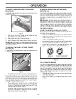
Fig. 9

Fig. 8

TO ADJUST MOWER CUTTING HEIGHT 

(See Fig. 9)

The position of the attachment lift lever (A) determines the 

cutting height.

A

•  Put attachment lift lever in desired cutting height slot.
The cutting height range is ap prox i mate ly 1" to 4". The 

heights are measured from the ground to the blade tip with 

the engine not running. These heights are approximate and 

may vary depending upon soil conditions, height of grass 

and types of grass being mowed.
•  The average lawn should be cut to approximately 

2-1/2" during the cool season and to over 3" during hot 

months. For healthier and better looking lawns, mow 

often and after moderate growth.

•  For best cutting performance, grass over 6" in height 

should be mowed twice. Make the first cut relatively 

high; the second to de sired height.

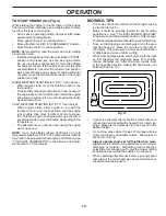
TO OPERATE MOWER

Your tractor is equipped with an operator presence sensing 

switch.  Any attempt by the operator to leave the seat with 

the engine running and the attachment clutch engaged will 

shut off the engine. You must remain fully and centrally 

positioned in the seat to prevent the engine from hesitat-

ing or cutting off when operating your equipment on rough, 

rolling terrain or hills.
• 

Select desired height of cut (see "TO ADJUST MOWER 

CUTTING HEIGHT")

•  Start mower blades by engaging at tach ment clutch 

control.

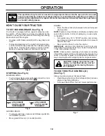
TO MOVE FORWARD AND BACKWARD 

(See Fig. 8)

The direction and speed of movement is controlled by the 

gearshift lever (J). 

1.  Start tractor with clutch/brake pedal depressed and 

gearshift lever in neutral position.

2.  Move gearshift lever to desired po si tion. 
3.  Slowly release clutch/brake pedal to start movement.

IMPORTANT:

 Bring tractor to a complete stop before shifting 

or changing gears. Failure to do so will shorten the useful 

life of your transaxle. 

J

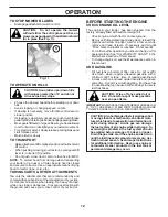
Fig. 10

REVERSE OPERATION SYSTEM (ROS) 

(See Fig. 10)

Your tractor is equipped with a Reverse Operation System 

(ROS). Any attempt by the operator to travel in the reverse 

direction with the attachment clutch engaged will shut off 

the engine unless ignition key is placed in the ROS "ON" 

position.

 WARNING:

  Backing up with the attachment clutch en-

gaged while mowing is strongly discouraged. Turning the 

ROS "ON", to allow reverse operation with the attachment 

clutch engaged, should only be done when the operator 

decides it is necessary to reposition the machine with the 

attachment engaged. 

Do not mow in reverse unless 

absolutely necessary

.

USING THE REVERSE OPERATION SYSTEM -

Only use if you are certain no children or other bystanders 

will enter the mowing area.
• 

Depress clutch/brake pedal all the way down and hold.

• 

With engine running, turn ignition key counterclockwise 

to ROS "ON" position.

•  Look down and behind before backing.
• 

Move gear shift lever to reverse (R) po si tion and slowly 

release clutch/brake pedal to start movement.

•  When use of the ROS is no longer needed, turn the 

ignition key clockwise to engine "ON" position.

ROS "ON" 

POSITION

ENGINE "ON" POSITION

(NORMAL OPERATING)

02828

Summary of Contents for 532438867R1

Page 1: ... Manual and follow all Warnings and Safety Instructions Failure to do so can result in serious injury IMPORTANT MANUAL DO NOT THROW AWAY 532 43 88 67 Rev 1 Gasoline containing up to 10 ethanol E10 is acceptable for use in this machine The use of any gasoline exceeding 10 ethanol E10 will void the product warranty 09 28 11 TH Printed in the U S A ...

Page 2: ...p all movement on the slopes slow and gradual Do not make sudden changes in speed or direction which could cause the machine to roll over Use extra care while operating machine with grass catch ers or other attachments they can affect the stability of the machine Do no use on steep slopes Do not try to stabilize the machine by putting your foot on the ground Do not mow near drop offs ditches or em...

Page 3: ...Use extra care when approaching blind corners shrubs trees or other objects that may block your view of a child IV TOWING Tow only with a machine that has a hitch designed for towing Do not attach towed equipment except at the hitch point Follow the manufacturer s recommendation for weight limits for towed equipment and towing on slopes Never allow children or others in or on towed equipment On sl...

Page 4: ...r this tractor Please read and retain this manual The instructions will enable you to assemble and maintain your tractor properly Always observe the SAFETY RULES CUSTOMER RESPONSIBILITIES Read and observe the safety rules Follow a regular schedule in maintaining caring for and using your tractor FollowtheinstructionsintheMaintenanceandStorage sections of this manual Wear proper Personal Protective...

Page 5: ...ED PARTS Steering Wheel Steering Wheel 1 Washer Seat 1 Seat Steering Boot Steering Extension Shaft Steering Wheel Adapter Key s Slope Sheet 1 Hex Bolt 1 Lock Washer 1 Large Flat Washer Steering Wheel Insert 1 Knob ...

Page 6: ...sition seated behind the steering wheel TOREMOVETRACTORFROMCARTON UNPACK CARTON Remove all accessible loose parts and parts cartons from carton Cut along dotted lines on all four panels of carton Remove end panels and lay side panels flat Check for any additional loose parts or cartons and remove BEFORE REMOVING TRACTOR FROM SKID TO INSTALL STEERING WHEEL See Fig 2 ASSEMBLE EXTENSION SHAFT AND BOO...

Page 7: ...ow the instructions below to remove the tractor from the skid WARNING Beforestarting read understandandfollow all instructions in the Operation section of this manual Be sure tractor is in a well ventilated area Be sure the area in front of tractor is clear of other people and objects TOROLLTRACTOROFFSKID SeeOperation section for location and function of controls Raise attachment lift lever to its...

Page 8: ...entify safety inform ation about hazards which can result in death serious injury and or property damage DANGER indicates a hazard which if not avoided will result in death or serious injury WARNING indicates a hazard which if not avoided could result in death or serious injury CAUTION indicates a hazard which if not avoided might result in minor or moderate injury CAUTION when used without the al...

Page 9: ... tractor and starting the engine C PARKING BRAKE Locks clutch brake pedal into the brake position D THROTTLE CHOKE CONTROL Used for starting and controlling engine speed Our tractors conform to the applicable safety standards of the American National Standards Institute E ATTACHMENT CLUTCH LEVER Used to engage the mowerblades orotherattachmentsmountedtoyourtractor F IGNITION SWITCH Used for starti...

Page 10: ... remain in brake position Make sure parking brake will hold tractor secure B C STOPPING See Fig 6 MOWER BLADES To stop mower blades place attachment clutch control in the DISENGAGED position GROUND DRIVE To stop ground drive depress clutch brake pedal into full BRAKE position Move gearshift lever J to neutral position ENGINE Move throttle control D between half and full speed fast position NOTE Fa...

Page 11: ...peed of movement is controlled by the gearshift lever J 1 Start tractor with clutch brake pedal depressed and gearshift lever in neutral position 2 Move gearshift lever to desired position 3 Slowly release clutch brake pedal to start movement IMPORTANT Bringtractortoacompletestopbeforeshifting or changing gears Failure to do so will shorten the useful life of your transaxle J Fig 10 REVERSE OPERAT...

Page 12: ...ment lift control When pushing or towing your tractor be sure gearshift lever is in neutral N position Do not push or tow tractor at more than five 5 MPH NOTE To protect hood from damage when transporting your tractor on a truck or a trailer be sure hood is closed and secured to tractor Use an appropriate means of tying hood to tractor rope cord etc BEFORE STARTING THE ENGINE CHECK ENGINE OIL LEVE...

Page 13: ...ments can also be used during the engine warm up period NOTE If at a high altitude above 3000 feet or in cold temperatures below 32 F 0 C thecarburetorfuelmixture may need to be adjusted for best engine performance See TO ADJUST CARBURETOR in the Service and Adjust ments section of this manual MOWING TIPS Tire chains cannot be used when the mower housing is attached to tractor Mower should be prop...

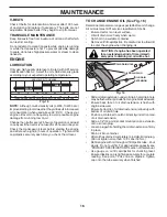
Page 14: ...ck Replace Mower Blades Che Clean Debris Off Steering Plate ck Transaxle Cooling Che Check Operator Presence ROS Systems ck V Belts Check Mower Levelness LUBRICATION CHART GENERAL RECOMMENDATIONS The warranty on this tractor does not cover items that have beensubjectedtooperatorabuseornegligence Toreceive full value from the warranty operator must maintain tractor as instructed in this manual Some...

Page 15: ...the ignition switch in the ROS ON position and the attachment clutch engaged any attempt by the operator to shift into reverse should NOT shut off the engine BLADE CARE For best results mower blade must be kept sharp Replace bent or damaged blade CAUTION Useonlyareplacementbladeap proved by the manufacturer of your tractor Using a blade not approved by the manu facturer of your tractor is hazardou...

Page 16: ...ssure water or steam to clean transaxle TO CHANGE ENGINE OIL See Fig 16 Determine temperature range expected before oil change All oil must meet API service classification SG SL Ensure tractor is on level surface Oil will drain more freely when warm Catch oil in a suitable container Remove oil fill cap dipstick Be careful not to allow dirt to enter the engine when changing oil Slide oil drain exte...

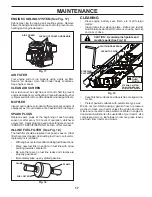
Page 17: ... line with arrow pointing towards carburetor Be sure there are no fuel line leaks and clamps are properly positioned Immediately wipe up any spilled gasoline Fig 18 ENGINE COOLING SYSTEM See Fig 17 Debris may clog the engine s air cooling system Remove blower housing and clean the area shown to prevent over heating and engine damage CLEAN OUT CHAFF AND DEBRIS 02744 AIR SCREEN Fig 19 Keep finished ...

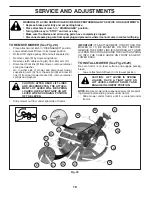
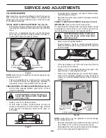
Page 18: ...O BE MOUNTED ON THE TRACTOR REMOVE THE FRONT LINK E AND REAR LIFT LINKS C FROM TRACTOR AND HOOK THE CLUTCH SPRING Q INTO THE CABLE GUIDE ON FRONT EDGE OF LOWER DASH TO INSTALL MOWER See Fig 20 25 Be sure tractor is on level surface and engage parking brake Lower attachment lift lever to it s lowest position CAUTION LIFT LEVER IS SPRING LOADED HAVE A TIGHT GRIP ON LIFT LEVER LOWER IT SLOWLY AND ENG...

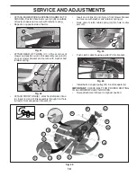
Page 19: ...and secure with retainer spring Repeat on opposite side of tractor ATTACH REAR LIFT LINKS C Lift rear corner of mower and position slot in link assembly over pin D on rear mower bracket and secure with washer and retainer spring Insert end of link E into hole in front mower bracket and secure with washer and retainer spring J Hook end of clutch cable spring Q into hole in idler arm R Push clutch c...

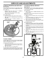
Page 20: ...nut will change mower height about 3 16 Test your adjustment by mowing some uncut grass and visually checking the appearance Readjust if necessary until you are satisfied with the results PRECISION SIDE TO SIDE ADJUSTMENT See Fig 27 With all tires properly inflated park tractor on level ground or driveway CAUTION Blade is sharp Protect your hands with gloves and or wrap blade with heavy cloth Rais...

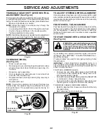
Page 21: ...tate then the brakeneedstobeserviced Contactaqualifiedservicecenter 02954 Manual A B D E F G TO REPLACE MOTION DRIVE BELT See Fig 31 Park the tractor on level surface Engage parking brake For assistance there is a belt installation guide decal on bottom side of left footrest BELT REMOVAL 1 Remove mower See TO REMOVE MOWER section in this manual NOTE Observe entire motion drive belt and position of...

Page 22: ...onwhenaround batteries If your battery is too weak to start the engine it should be recharged See BATTERY in the MAINTENANCE sec tion of this manual If jumper cables are used for emergency starting follow this procedure IMPORTANT YOUR TRACTOR IS EQUIPPED WITH A 12 VOLT SYSTEM THE OTHER VEHICLE MUST ALSO BE A 12 VOLT SYSTEM DO NOT USE YOUR TRACTOR BATTERY TO START OTHER VEHICLES TO ATTACH JUMPER CA...

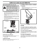
Page 23: ...e or damaged wiring may cause your tractor to run poorly stop running or prevent it from starting Check wiring TO REPLACE FUSE Replace with 20 amp automotive type plug in fuse The fuse holder is located behind the dash ENGINE TO ADJUST THROTTLE CONTROL CABLE The throttle control has been preset at the factory and adjustment should not be necessary If adjustment is nec essary see engine manual TO A...

Page 24: ...ENTIALFUELSYSTEMPARTSSUCH AS CARBURETOR FUEL FILTER FUEL HOSE OR TANK DURING STORAGE ALSO EXPERIENCE INDICATES THAT ALCOHOL BLENDED FUELS CALLED GASOHOL OR USING ETHANOLORMETHANOL CANATTRACTMOISTUREWHICH LEADSTOSEPARATIONANDFORMATIONOFACIDSDURING STORAGE ACIDIC GAS CAN DAMAGE THE FUEL SYSTEM OF AN ENGINE WHILE IN STORAGE Empty the fuel tank by starting the engine and let it run until the fuel line...

Page 25: ...own fuse 4 Replace fuse 5 Corroded battery terminals 5 Clean battery terminals 6 Loose or damaged wiring 6 Check all wiring 7 Faulty ignition switch 7 Check replace ignition switch 8 Faulty solenoid or starter 8 Check replace solenoid or starter 9 Faulty operator presence switch es 9 Contact an authorized service center department Engine clicks but will not start 1 Weak or dead battery 1 Recharge ...

Page 26: ... Replace blade Tighten blade bolt 7 Buildup of grass leaves and trash under mower 7 Clean underside of mower housing 8 Mower drive belt worn 8 Replace mower drive belt 9 Blades improperly installed 9 Reinstall blades sharp edge down 10 Improper blades used 10 Replace with blades listed in parts manual 11 Cloggedmowerdeckventholesfrombuildup of grass leaves and trash around mandrels 11 Clean around...

Page 27: ... never across the face Do not mow slopes greater than 15 degrees Make turns gradually to prevent tipping or loss of control Exercise extreme caution when changing direction on slopes 1 Fold this page along dotted line indicated above 2 Hold page before you so that its left edge is vertically parallel to a tree trunk or other upright structure 3 Sight across the fold in the direction of hill slope ...

Page 28: ...used for rental or commercial purposes is limited to 90 days from the date of origi nal purchase 5 This Warranty applies only to products which have been properly assembled adjusted operated and maintained in ac cordance with the instructions furnished This Warranty does not apply to any product which has been subjected to altera tion misuse abuse improper assembly or installation delivery damage ...

Page 29: ...29 SERVICE NOTES ...
Page 30: ...turer s I D Number b Description of part For Technical Assistance call 1 800 829 5886 For a Parts Manual go to our website www poulan com NOTE HOP provides parts and service through its authorized distributors and dealers therefore all requests for parts and service should be directed to your local dealer s The philosophy of HOP is to continually improve all of its products If the operating charac...

Reviews: