background image

20

SERVICE AND ADJUSTMENTS

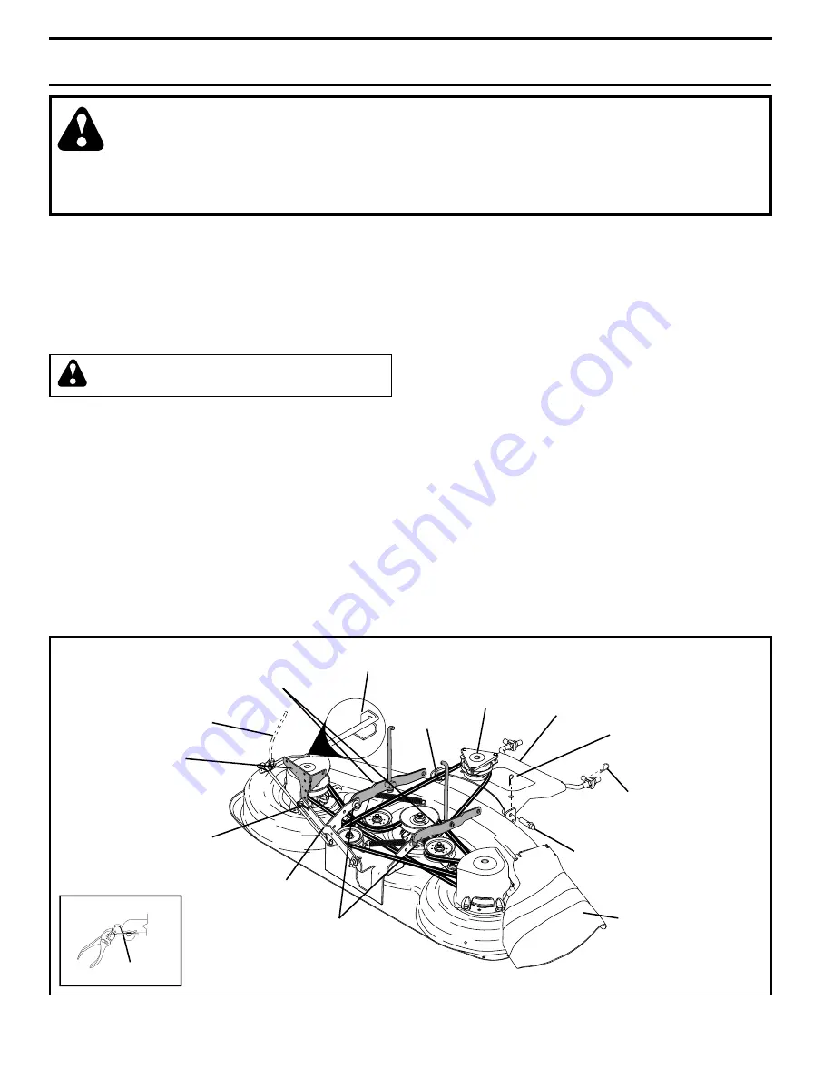
TO REMOVE MOWER  (See Fig. 19)

•      Place attachment clutch in “DIS EN GAGED” position.
•    If equipped, turn height adjustment knob to low 

est 

set ting.

•      Lower mower to its lowest position.
•      Disengage belt tension rod from lock bracket.

CAUTION: Rod is spring loaded. Have a 
tight grip on rod and release slowly.

•        Remove retainer spring holding anti-swaybar to chas sis 

bracket and dis en gage anti-swaybar from bracket.

•        Remove four retainer springs from front plate assembly 

and remove plate.

•      Remove retainer springs from sus pen sion arms at deck 

and dis en gage arms from deck.

•      Raise attachment lift to its highest position.
       Slide  mower  forward  and  remove  belt  from  electric 

clutch pulley.

•      Slide mower out from under right side of tractor.

TO INSTALL MOWER

Be sure tractor is on level surface and mower suspension 
arms are raised with attachment lift control. Engage park-
 ing brake.
•      Swing anti-sway bar to left side of mower deck.
•      Slide mower under tractor with defl ector shield to right 

side of tractor.

IMPORTANT: 

 CHECK BELT FOR PROPER ROUTING IN ALL 

MOWER PULLEY GROOVES.  

•      If  equipped,  turn  height  ad just ment knob coun 

ter -

clock wise until it stops.

•      Lower mower linkage with attachment lift control.
•      Be sure belt tension rod is in dis en gaged position.
•      Install belt into electric clutch pulley groove.
•      Place the suspension arms on outward pointing deck 

pins.  Retain with double loop re tain er spring with loops 
up as shown.

•    Install front plate assembly to tractor suspension 

brack ets and retain with single loop retainer springs 
as shown.

•    Position front plate assembly between front mower 

brackets. Raise deck and plate assembly to align holes 
and insert fl anged pins. Secure pins with double loop 
retainer springs between the plate assembly and mower 
brack ets.

SUS PEN SION 
ARMS

RE TAIN ER SPRING

ANTI-SWAY 
BAR

SUSPENSION ARMS DOUBLE 
LOOP RE TAIN ER SPRINGS 
(Out ward pointing deck pins)

CHAS SIS 
BRACK ET

SINGLE LOOP 
RETAINER 
SPRING

FRONT 
MOWER 
BRACKET

FLANGED PIN

ELEC TRIC 
CLUTCH 
PULLEY

FRONT 
PLATE 
AS SEM BLY

BELT TENSION  ROD 
(DIS EN GAGED POSITION)

DOUBLE LOOP 
RETAINER 
SPRING

DE FLEC TOR 
SHIELD

LOCK BRACK ET

USE PLIERS FOR

RETAINER SPRINGS

LOOP UP

FIG. 19

WARNING: TO AVOID SERIOUS INJURY, BEFORE PERFORMING ANY SER VICE OR AD JUST MENTS:


Depress brake pedal fully and set parking brake.


Place attachment clutch  in “DISENGAGED” position.


Turn ignition key to “STOP” and remove key.


Make sure the blades and all moving parts have completely stopped.


Disconnect spark plug wire from spark plug and place wire where it cannot come in contact  

 with 

plug.

TRACTOR

Summary of Contents for PDGT26H48B

Page 1: ... S MANUAL MODEL PDGT26H48B LAWN TRACTOR Always Wear Eye Protection During Operation WARNING Read the Owner s Manual and fol lowallWarningsandSafetyInstruc tions Failure to do so can result in serious injury IMPORTANT MANUAL Do Not Throw Away 00993 poulan_pro ...

Page 2: ... changes in speed or direction Avoid starting or stopping on a slope If tires lose trac tion disengage the blades and proceed slowly straight down the slope SAFETY RULES SAFE OPERATION PRACTICES FOR RIDE ON MOWERS IMPORTANT THIS CUTTING MACHINE IS CAPABLE OF AMPUTATING HANDS AND FEET AND THROWING OBJECTS FAILURE TO OBSERVE THE FOLLOWING SAFETY INSTRUCTIONS COULD RESULT IN SERIOUS INJURY OR DEATH D...

Page 3: ...n even with the blades off Do not mow in reverse unless absolutely necessary Always look down and behind before and while backing Nevercarrychildren Theymayfalloffandbeseriouslyinjured or interfere with safe machine operation Keep children out of the mowing area and under the watchful care of another responsible adult Be alert and turn machine off if children enter the area Before and when backing...

Page 4: ...s manual WARNING This tractor is equipped with an internal com bustion engine and should not be used on or near any unimprovedforest covered brush coveredorgrass covered land unless the engine s exhaust system is equipped with a spark arrester meeting applicable local or state laws if any If a spark arrester is used it should be maintained in effective working order by the operator A spark arreste...

Page 5: ...Tube For Future Use 4 Shoulder Bolt Steering Wheel Steering Wheel Insert Seat Mower 1 Front Plate Assembly 5 Retainer Springs double loop 2 Retainer Springs single loop 2 Flanged Pins Premium Steering Adapter Steering Sleeve Steering Sleeve Extension 1 Knob 1 Washer 17 32 x 1 3 16 x 12 Gauge Nose Roller Nose Roller Brackets 2 Hex Bolts 5 16 18 x 1 2 Locknuts 5 16 18 Rod Retainer Spring ...

Page 6: ...T WASHER STEERING WHEEL STEERING WHEEL ADAPTOR STEERING SLEEVE EX TENTION TABS STEERING SHAFT STEERING SLEEVE BEFORE REMOVING TRACTOR FROM SKID ATTACH STEERING WHEEL See Fig 1 Remove hex bolt lock washer and large flat washer from steering shaft Position front wheels of the tractor so they are pointing straight forward Slide the steering sleeve over the steering shaft Align tabs and press steering...

Page 7: ... to tractor assembly raise gauge wheels to highest position and retain with clevis pins and spring retainers Adjust gauge wheels before operating mower See TO ADJUST GAUGE WHEELS in the Operation section of this manual SHOULDER BOLT GAUGE WHEEL 3 8 16 CENTER LOCKNUT 3 8 WASHER ADJUSTING BAR PIN RETAINER SPRING TO ROLL TRACTOR OFF SKID See Op eration section for location and function of controls Pr...

Page 8: ...essary move mowerside to sidetogivespacebetweenplateandmower brackets IMPORTANT Check belt for proper routing in all mower pulley grooves Engage belt tension rod by pushing rod into locking bracket Engage belt tension rod by pushing rod into locking bracket CAUTION Belt tension rod is spring loaded Have a tight grip on rod and engage slowly Connect anti sway bar to chassis bracket under left footr...

Page 9: ...THE FOLLOWING IMPORTANT ITEMS Engine oil is at proper level Fuel tank is filled with fresh clean regular unleaded gasoline Become familiar with all controls their location and function Operate them before you start the engine Be sure brake system is in safe operating condition It is important to purge the transmission before oper ating your tractor for the first time Follow proper start ing and tr...

Page 10: ... could result in serious injury or death The safety alert symbol is used to identify safety inform ation about hazards which can result in death serious injury and or property damage DANGER indicates a hazard which if not avoided will result in death or serious injury WARNING indicates a hazard which if not avoided could result in death or serious injury CAUTION indicates a hazard which if not avo...

Page 11: ... PLUNGER Used to release attachment lift lever when changing its position HOURMETER Indicates hours of operation THROTTLE CONTROL Used to control engine speed FREEWHEEL CONTROL Disengages transmission for pushing or slowly towing the tractor with the engine off IGNITION SWITCH Used to start and stop the engine AMMETER Indicates battery charging or discharg ing PARKING BRAKE LEVER Locks brake pedal...

Page 12: ... cutting performance grass over 6 inches in height should be mowed twice Make the first cut relatively high the second to desired height TO USE CHOKE CONTROL See Fig 8 Use choke control whenever you are starting a cold engine Do not use to start a warm engine knob in to disengage TO USE THROTTLE CONTROL See Fig 8 Always operate engine at full throttle Operating engine at less than full throttle re...

Page 13: ... greater than 15 and do not drive across any slope Choose the slowest speed before starting up or down hills Avoid stopping or changing speed on hills If stopping is absolutely necessary push brake pedal quickly to brake position and engage parking brake IMPORTANT THE MOTION CONTROL LEVER RETURNS TO NEUTRAL N POSITION WHEN THE BRAKE PEDAL IS FULLY DEPRESSED To restart movement slowly release parki...

Page 14: ...ed to disengage the motion drive belt as follows Be sure parking brake is engaged BEFORE STARTING THE ENGINE CHECK ENGINE OIL LEVEL The engine in your tractor has been shipped from the factory already filled with summer weight oil Check engine oil with tractor on level ground Remove oil fill cap dipstick and wipe clean reinsert the dipstick and screw cap tight wait for a few seconds remove and rea...

Page 15: ...Start engine and allow it to warm up for three 3 min utes Shut off engine and engage parking brake Engage drive belt tension handle and replace the retainer spring AUTOMATIC TRANSMISSION WARM UP Beforedrivingtheunitincoldweather thetransmission should be warmed up as follows Be sure the tractor is on level ground Place the motion control lever in neutral Re lease the parking brake and let the brak...

Page 16: ...e warranty on this tractor does not cover items that have beensubjectedtooperatorabuseornegligence Toreceive full value from the warranty operator must maintain tractor as instructed in this manual Some adjustments will need to be made periodically to properly maintain your tractor All adjustments in the Service and Adjustments section of this manual should be checked at least once each season Onc...

Page 17: ...loth Remove blade bolt by turning counterclockwise Install new or resharpened blade with stamped THIS SIDE UP facing deck and mandrel assembly IMPORTANT TO ENSURE PROPER ASSEMBLY CENTER HOLE IN BLADE MUST ALIGN WITH STAR ON MANDREL ASSEMBLY Install and tighten blade bolt securely 45 55 Ft Lbs torque IMPORTANT SPECIAL BLADE BOLT HEAT TREATED TO SHARPEN BLADE See Fig 14 NOTE We do not recommend shar...

Page 18: ...ll cap dipstick securely each time you check the oil level TEMPERATURE RANGE ANTICIPATED BEFORE NEXT OIL CHANGE SAE VISCOSITY GRADES 20 0 30 40 80 100 30 20 0 20 30 40 F C 32 10 10 60 5W 30 SAE 30 oil_visc_chart1_e FIG 16 FIG 15 TO CHANGE ENGINE OIL See Figs 15 and 16 Determine temperature range expected before oil change All oil must meet API service classification SF SJ Be sure tractor is on lev...

Page 19: ...irty or damaged replace pre cleaner TO SERVICE CARTRIDGE Clean cartridge by tapping gently on flat surface If very dirty or damaged replace cartridge Reinstall precleaner cartridge cover and secure with knobs IMPORTANT PETROLEUMSOLVENTS SUCHASKEROSENE ARE NOT TO BE USED TO CLEAN THE CARTRIDGE THEY MAY CAUSE DETERIORATION OFTHE CARTRIDGE DO NOT OILCARTRIDGE DONOTUSEPRESSURIZEDAIRTOCLEAN OR DRY CART...

Page 20: ... attachment lift control Be sure belt tension rod is in disengaged position Install belt into electric clutch pulley groove Place the suspension arms on outward pointing deck pins Retain with double loop retainer spring with loops up as shown Install front plate assembly to tractor suspension brackets and retain with single loop retainer springs as shown Position front plate assembly between front...

Page 21: ...N Blades are sharp Protect your hands with gloves and or wrap blade with heavy cloth Checkadjustmentonrightsideoftractor Positionanyblade so the tip is pointing straight forward Measure distance B at front and rear tip of the blade Before making any necessary adjustments check that both front plate links are equal in length If links are not equal in length adjust one link to same length as other l...

Page 22: ...VE BELT REMOVAL See Fig 24 Park tractor on a level surface Engage parking brake Lower mower to its lowest position Disengage belt tention rod from lock bracket CAUTION Rod is spring loaded Have a tight grip on rod and release slowly Remove screws from R H mandrel cover and remove cover Remove any dirt or grass clippings which may have accumulated around mandrels and entire upper deck surface Disco...

Page 23: ... DRIVE BELT Refer to TO REMOVE MOWER DRIVE BELT illustration in this section of manual Carefully roll belt over the top of R H mandrel pulley Remove belt from idler pulleys Check primary idler arm and two idlers to see that they rotate freely Be sure spring is securely hooked to primary idler arm and spring arm REMOVE MOWER BLADE SECONDARY DRIVE BELT Carefully roll belt off L H mandrel pulley Remo...

Page 24: ... on bottom of left footrest Remove mower See TO REMOVE MOWER in this section of this manual BELT REMOVAL Create slack in belt by removing retainer spring from drive belt tension handle Remove belt from all idler pulleys transaxle pulley and then from engine pulley BELT INSTALLATION Install new belt around engine pulley first then around transaxle pulley and lastly into all the idler pulleys Check ...

Page 25: ...d battery Reinstall terminal guard First connect RED battery cable to positive battery terminal with hex bolt and keps nut as shown Tighten securely ConnectBLACKgroundingcabletonegative battery terminal with remaining hex bolt and keps nut Tighten securely Close terminal access doors Close hood WEAK OR DEAD BATTERY FULLY CHARGED BATTERY FIG 30 TO START ENGINE WITH A WEAK BATTERY See Fig 30 WARNING...

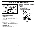
Page 26: ...ng See electrical wiring diagram in the Repair Parts section TO REPLACE FUSE Replace with 30 amp automotive type plug in fuse The fuse holder is located behind the dash SERVICE AND ADJUSTMENTS 02141 HEADLIGHT WIRE CONNECTOR FIG 32 HOOD TO REMOVE HOOD AND GRILL ASSEMBLY See Fig 32 Raise hood Unsnap headlight wire connector Stand in front of tractor Grasp hood at sides tilt toward engine and lift of...

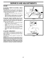
Page 27: ...ws With engine not running move choke control located on dash panel to full choke position Loosen knob and remove cover assembly from air cleaner Chokeshouldbeclosed Ifitisnot loosencasingclamp screw and move choke cable until choke is completely closed Tighten casing clamp screw securely Replace air cleaner cover assembly and tighten knob TO ADJUST CARBURETOR Your carburetor is not adjustable If ...

Page 28: ...AL FUEL SYSTEM PARTS SUCH AS CARBURETOR FUEL FILTER FUEL HOSE OR TANK DURING STORAGE ALSO EXPERIENCE INDICATES THAT ALCOHOL BLENDED FUELS CALLED GASOHOL OR USING ETHANOLORMETHANOL CANATTRACTMOISTUREWHICH LEADSTOSEPARATIONANDFORMATIONOFACIDSDURING STORAGE ACIDIC GAS CAN DAMAGE THE FUEL SYSTEM OF AN ENGINE WHILE IN STORAGE Drain the fuel tank Start the engine and let it run until the fuel lines and ...

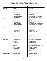
Page 29: ...ing 6 Check all wiring 7 Faulty ignition switch 7 Check replace ignition switch 8 Faulty solenoid or starter 8 Check replace solenoid or starter 9 Faulty operator presence switch es 9 Contact an authorized service center department Engine clicks but will not 1 Weak or dead battery 1 Recharge or replace battery start 2 Corroded battery terminals 2 Clean battery terminals 3 Loose or damaged wiring 3...

Page 30: ...rpen blade Tighten blade bolt 7 Buildup of grass leaves and trash under mower 7 Clean underside of mower housing 8 Mower drive belt worn 8 Replace mower drive belt 9 Blades improperly installed 9 Reinstall blades sharp edge down 10 Improper blades used 10 Replace with blades listed in this manual 11 Clogged mower deck vent holes from buildup of 11 Clean around mandrels to open vent holes grass lea...

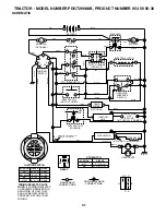
Page 31: ...ON LIGHTS B S A1 START M G A1 B A1 ON MAKE L A2 NONE NONE NONE OPTIONAL HEADLIGHTS BLACK ELECTRIC CLUTCH CLUTCH BRAKE PEDAL UP PTO DISENGAGED C G F B E A D H RED GREEN GREEN BLUE RED RED RED WHITE WHITE WHITE BLACK HOUR METER OPTIONAL STARTER PTO SWITCH CIRCUIT POSITION OFF C F B E A D ON C G B H B A G H D F C E IGNITION SWITCH G B S M A1 A2 L OPERATOR PRESENCE RELAY 1 85 86 30 87 87A SEAT SWITCH ...

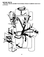
Page 32: ...32 30 33 24 42 43 40 26 28 25 50 29 27 27 41 16 12 12 11 10 8 2 1 27 D C AMPERES 45 81 46 89 22 79 21 REPAIR PARTS TRACTOR MODEL NUMBER PDGT26H48B PRODUCT NUMBER 954 56 95 30 ELECTRICAL ...

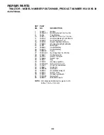
Page 33: ...22 4152J Bulb Light 24 185464 Cable Battery 25 146149 Cable Battery 26 108824X Fuse 27 73510400 Nut Keps Hex 1 4 20 Unc 28 170697 Cable Ground 29 160784 Switch Plunger 30 175566 Switch Ign 33 140401 Key 40 170238 Harness Ignition 41 17720408 Screw 1 4 20 x 1 2 42 131563 Cover Terminal Red 43 178861 Solenoid 45 122822X Ammeter 46 169635 Hourmeter Snap In 50 174653 Switch PTO 79 175242 Socket Light ...

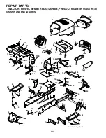
Page 34: ...ES 31 68 43 34 47 24 39 17 86 166 2 19 20 16 17 56 21 47 17 28 91 1 36 36 50 17 17 8 156 156 156 152 159 6 7 7 7 30 45 17 35 5 14 18 130 130 144 17 130 142 17 130 32 17 139 17 33 139 122 150 167 122 148 153 130 157 158 37 17 17 58 161 162 138 17 17 17 17 44 99 146 143 47 165 chassis stealth_37 vgt ...

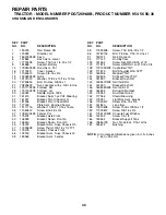
Page 35: ...ket Asm Susp Chassis Rh 47 17490608 Screw Thdrol 3 8 16 x 1 2 TYT 50 175476 Bracket Chassis Front 56 176016 Bracket Asm Susp Chassis Lh 58 183569 Bracket Asm Fender 68 17490508 Screw Thd 5 16 18 x 1 2 86 74780716 Bolt Fin Hex 7 16 14 Unc x 1 91 180374 Rail Frame Lh 99 177143 Rod By Pass 122 161464 Screw Hex Wshd 8 18 x 7 8 130 171875 Screw HWHD Hi Lo 13 16 x 3 4 138 179125X428 Cupholder YTGT 139 1...

Page 36: ... 130 131 34 35 37 38 40 41 42 68 46 36 37 38 64 39 56 29 89 132 77 70 74 89 120 89 133 120 98 112 123 94 94 126 138 23 114 73 120 127 153 143 48 120 117 52 129 50 117 48 128 142 58 77 152 151 135 137 6 22 124 125 111 121 122 114 20 147 146 61 1 2 2 69 33 3 145 107 106 108 145 69 33 3 117 drive_6 vgt ...

Page 37: ...rew Hex Wsh Hi Lo 1 4 1 2 77 74780716 Bolt Fin Hex 7 16 14 x 1 89 73680700 Nut Crownlock 7 16 14 Unc 94 133835 Fastener Christmas Tree 98 141004 Bracket Shift 106 142917 Cap Asm Vent Hydro Gear 107 154739 Line Fuel Hydro 15 VGT 108 142918 O Ring Asm Hydro Gear 111 156240 Spacer Shift Lever VGTH 112 178558 Washer Nylon High Temp 114 73800500 Nut Lock Hex W Ins 5 16 18 Unc 117 73900600 Nut Lock Flg ...

Page 38: ...H48B PRODUCT NUMBER 954 56 95 30 STEERING ASSEMBLY 47 48 46 49 50 8 6 29 28 23 31 41 22 21 20 1 45 14 25 34 33 32 6 27 42 27 6 19 15 14 35 18 16 9 8 7 2 6 6 4 14 15 14 14 15 12 9 3 8 7 3 6 6 5 13 13 7 8 14 15 14 36 14 26 10 11 steering_10 vgt 14 ...

Page 39: ...ing Vgt 20 163887X428 Boot Steering Stealth 21 159945 Adapter Wheel Steering 22 155105 Bushing Strg 23 152927 Screw 25 74780616 Bolt Fin Hex 3 8 16 x 1 Gr 5 26 180657 Insert Cap Strg WH 27 3366R Bearing Col Strg 28 17000612 Screw Hexwsh thdr 3 8 16 x 3 4 29 104239X Bearing Flange 31 138136 Bushing Nyliner Snap 32 19111610 Washer 11 32 x 1 x 10 Ga 33 10040500 Washer Lock Hvy Hlcl Spr 5 16 34 747805...

Page 40: ...Clip REPAIR PARTS TRACTOR MODEL NUMBER PDGT26H48B PRODUCT NUMBER 954 56 95 30 ENGINE 1 84 24 12 11 41 42 43 10 9 8 40 29 SPARK ARRESTER KIT 84 45 47 39 18 15 37 28 37 27 26 22 25 21 20 74 62 71 70 79 69 83 2 81 82 31 engine intek ELS_10 vgt KEY PART NO NO DESCRIPTION 37 123487X Clamp Hose 39 17490636 Screw TT 3 8 16 x 2 1 4 Unc 40 17490664 Screw TT 3 8 16 x 4 Unc 41 126197X Washer 1 1 2 OD x 15 32...

Page 41: ... Jam Hex 1 2 13 Unc 26 73680800 Nut Crownlock 1 2 13 Unc 29 150233 Trunnion Inf Height 30 110807X Nut Special 31 19131016 Washer 13 32 x 5 8 x 16 Ga 32 137150 Spring Compression Inf Hgt 33 76020308 Pin Cotter 3 32 x 1 2 NOTE All component dimensions given in U S inches 1 inch 25 4 mm KEY PART NO NO DESCRIPTION 34 137167 Rod Adj Lift 35 138057 Knob Inf 3 8 16 Unc 38 155097 Pointer Height Indicator ...

Page 42: ...8X Bushing Snap 14 72050412 Bolt Carriage 1 4 20 x 1 1 2 15 121249X Spacer Split 16 123740X Spring Cprsn 17 123976X Nut Lock 1 4 Lg Flg Gr 5 18 19171912 Washer 17 32 x 1 3 16 x 12 Ga 19 166369 Knob Seat 20 124238X Cap Spring Seat Blk 21 171852 Bolt 5 16 18 Unc 2A 37 73800500 Nut Crownlock 5 16 18 38 19131610 Washer Flat 13 32 x 1 x 10 Ga 39 71110616 Bolt 3 8 16 x 1 KEY PART NO NO DESCRIPTION 1 10 ...

Page 43: ...cal Battery 23 106202X Reflector Taillight 29 176651 Decal Fender Auto Trans 179769X428 Pad Footrest RH 179768X428 Pad Footrest LH 186714 Manual Owner s English 186715 Manual Owner s French KEY PART NO NO DESCRIPTION WHEELS TIRES 6 12 2 1 3 11 4 10 5 9 8 7 wheel_art_1 vgt 1 59192 Cap Valve Tire 2 65139 Stem Valve 3 106228X421 Rim Assembly Front 4 8134H Tube Front Service Item Only 5 161024 Tire Fr...

Page 44: ...1 94 182 95 183 132 48_nose_roller 57 56 118 116 119 5 117 46 45 33 46 45 33 30 30 30 32 39 21 20 18 21 31 1 32 31 36 36 52 24 25 26 27 28 29 18 8 11 13 16 100 113 17 48 19 5 6 3 14 15 47 49 49 49 49 130 43 121 126 97 115 50 50 98 42 99 42 114 110 112 21 122 42 97 36 37 184 mower_deck 48prem_2 ...

Page 45: ...968 Pulley Idler Flat 39 174375 Pulley Idler Driven 42 122052X Spacer Retainer 43 174373 Arm Idler Secondary 45 180806 Cover Mandrel Deck 46 137729 Screw Thdroll 1 4 20 x 5 8 47 180808 V Belt Mower Secondary 48 174368 V Belt Mower Primary 49 73680600 Nut Crownlock 3 8 16 Unc 50 72110612 Bolt Carr 3 8 16 x 1 1 2 Gr 5 52 175820 Pulley Idler Flat 56 155986 Bar Pnt Adj 57 156941 Pin Head Rivet 91 1805...

Page 46: ...d for rental or commercial purposes is limited to 90 days from the date of original purchase 5 This Warranty applies only to products which have been properly assembled adjusted operated and main tained in accordance with the instructions furnished This Warranty does not apply to any product which has been subjected to alteration misuse abuse improper assembly or installation delivery damage or to...

Page 47: ...the face Do not mow slopes greater than 15 degrees Make turns gradually to prevent tipping or loss of control Exercise extreme caution when changing direction on slopes 1 Fold this page along dotted line indicated above 2 Hold page before you so that its left edge is vertically parallel to a tree trunk or other upright structure 3 Sight across the fold in the direction of hill slope you want to me...

Page 48: ...rimmers Brushcutters and Blowers 3 For replacement parts have available the following information a Model Number Manufacturer s I D Number b Description of part NOTE Electrolux Home Products provides parts and service through its authorized distributors and dealers therefore all requests for parts and service should be directed to your local dealer s The philosophy of Electrolux Home Products is t...

Reviews: