background image

Summary of Contents for PO5524

Page 1: ...AL MODEL NUMBER PR8527ES SNOW THROWER WARNING Read the Owner s Manual and follow all Warnings and Safety Instructions Failure to do so can result in serious injury Always Wear Eye Protection During Operation 199375Rev 4 06 01 06 BY Printed in U S A ...

Page 2: ...perate the equipment without wearing adequate winter garments Avoid loose fitting clothing that can get caught in moving parts Wear footwear that will improve footing on slippery surfaces 4 Handle fuel with care it is highly flammable a Use an approved fuel container b Never add fuel to a running engine or hot en gine c Fill fuel tank outdoors with extreme care Never fill fuel tank indoors d Never...

Page 3: ...ondition 2 Never store the machine with fuel in the fuel tank inside a building where ignition sources are present such as hot water heaters space heaters or clothes dryers Allow the engine to cool before storing in any enclosure 3 Always refer to operator s manual for important details if the snow thrower is to be stored for an extended period 4 Maintain or replace safety and instruction labels a...

Page 4: ...ch as nuts washers bolts etc necessary to complete the assembly have been placed in the parts bag To ensure safe and proper operation of your snow thrower all parts and hardware you assemble must be tightened securely Use the correct tools as necessary to ensure proper tightness REMOVE SNOW THROWER FROM CARTON 1 Remove all accessible loose parts and parts boxes from carton 2 Out down all four corn...

Page 5: ...e with retainer spring SPEED CONTROL i LOWER HANDLE FIG 1 SPEED CONTROL ROD RETAINER SPRING SPEED SPEED CONTROL CONTROL BRACKET LEVER INSTALL TRACTION DRIVE CONTROL ROD See Figs 3 and 4 The traction drive control rod has the long loop on the end of the spring as shown 1 Slide rubber sleeve up rod and hook end of spring into pivot bracket with loop opening down as shown 2 With top end of rod positi...

Page 6: ...ater head 1 Place discharge chute assembly on top of chute base with discharge opening toward front of snow thrower 2 Positionchuterotaterheadoverchutebracket Ifneces sary rotate chute assembly to align square and pinon un derside of chute rotate rhead with holes inchute bracket 3 With chute rotater head and chute bracket aligned position chute rotater head on pin and threaded stud of mounting bra...

Page 7: ...re reference These symbols may appear on your snow thrower or in literature supplied with the product Learn and understand their meaning ENGINE OFF I 1 r DANGER ENGINE FAST SLOW CHOKE PRIMER OR WARNING ON FUEL OIL FORWARD REVERSE READ AND FOLLOW ALL SAFETY iNFORMATiON AND iNSTRUCTiONS BEFORE USE OF THiS PRODUCT KEEP THESE iNSTRUCTiONS FOR FUTURE REFERENCE iGNiTiON KEY iNSERT TO START AND RUN PULL ...

Page 8: ...ds Institute Toolbox used to store spare shear bolts locknuts and wrench Safety ignition key must be inserted for the engine to start and run Remove when snow thrower is not in use Electric start button used for starting the engine Recoil auxiliary starter handle used for starting the engine Primer pumps additional fuel from the carburetor to the cylinder for use when starting a cold engine Choke ...

Page 9: ... Slowly turn knob counterclockwise to disengage FULL FIG 11 TO CONTROL SNOW DISCHARGE See Figs 12 13 WARNING Snow throwers have ex posed rotating parts which can cause severe injury from contact or from ma terial thrown from the discharge chute Keep the area of operation clear of all persons small children and pets at all times including startup WARNING If the discharge chute or au ger become clog...

Page 10: ...t the engine then squeeze the auger control lever to the handle to clear snow from the auger hous ing and the discharge chute DISCHARGE CHUTE TOOL FIG 15 TO MOVE FORWARD AND BACKWARD See Fig 16 SELF PROPELLING forward and reverse movement of the snow thrower is controlled by the traction drive control lever located on the left side handle Squeeze traction drive control lever to handle to engage th...

Page 11: ...it for a few seconds remove and read oil level If necessary add oil until FULl mark on dipstick is reached Do not overfill To change engine oil see TO CHANGE ENGINE Oil in the Maintenance section of this manual ADD GASOLINE See Fig 18 Fill fuel tank to bottom of tank filler neck Do not over fill Use fresh clean regular unleaded gasoline with a minimum of 87 octane Do not mix oil with gasoline Purc...

Page 12: ... the engine To avoid possible freeze up of the starter proceed as fol lows ELECTRIC STARTER 1 Connect the power cord to the engine 2 Plug the other end of the power cord into a three hole grounded 120 Volt A C receptacle 3 While the engine is running push starter button and spin the starter for several seconds NOTE The unusual sound made while starter is spinning will not harm the engine or starte...

Page 13: ...nit to malfunction and pose a risk of injury to the operator BEFORE EACH USE 1 Check engine oil level 2 Check for loose fasteners 3 Check controls to be sure they are functioning properly LUBRICATION Keep your snow thrower well lubricated See LUBRICATION CHART LUBRICATION CHART SAE 30 Motor Oil See ENGINE in Maintenance section Engine oil SNOW THROWER Always observe the safety rules when performin...

Page 14: ...removed from snow thrower for easier access to the oil drain plug and place ment of a suitable container The unit tilted resting on the frame with the left wheel removed will help drain any oil trapped inside the engine See TO REMOVE WHEELS in the Service and Adjustments section of this manual 1 Disconnect spark plug wire from spark plug and place wire where it cannot come in contact with plug 2 C...

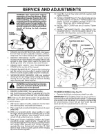
Page 15: ...shear bolts as supplied with your I snow thrower 4 Connect spark plug wire to spark plug IMPELLER SHEAR BOLTS The impeller is secured to the impeller shaft with two 2 capscrew shear bolts and hex nuts Should a foreign object or ice become lodged in the impeller the capscrews are designed to break preventing damage to any other com ponents If impeller does not turn when auger control lever is engag...

Page 16: ... in the operating position holding the handles remove the two 2 bolts and lock washers holding auger housing and frame together I WARNING Asthelast bolt is removed I have your assistant carefully lower the handles down to the ground 6 REMOVE AUGER BELT from around pulley 7 RELIEVETENSION ONTRACTION DRIVE BELTIDLER and remove traction drive belt from around pulleys HINT Insert a 3 8 drive ratchet i...

Page 17: ... if necessary Touch up all rusted or chipped paint surfaces sand lightly before painting ENGINE See engine manual FUEL SYSTEM IMPORTANT It is important to prevent gum deposits from forming in essential fuel system parts such as carburetor fuel hose ortank during storage Also alcohol blended fuels called gasohol or using ethanol or methanol can attract moisture which leads to separation and formati...

Page 18: ... is worn 1 Auger belt is off of pulley 2 Auger belt is worn 3 Clogged discharge chute 4 Augers impeller jammed 2 Insert safety ignition key 3 Fill fuel tank 4 Move throttle to FAST position 5 Move to FULL position 6 Prime as instructed in the Operation section of this manual 7 Wait a few minutes before restarting DO NOT prime 8 Connect wire to spark plug 9 Replace spark plug 10 Drain fuel tank and...

Page 19: ...SERVICE NOTES 19 ...

Page 20: ...HROWER MODEL NO PR8527ES 96192000300 AUGER HOUSING IMPELLER ASSEMBLY 16 4 6Y_ 13 15 __6 6 12 _ 10 141 5 9 11 33 34 f t X J l 51 36 44 45 27 55 46 10 38 42 43 47 18 56 10 35 55 29 23 31 21 27 18 22 26 30 57 25 20 23 24 20 ...

Page 21: ...rust 1 28 192090 Bolt Shear 29 174762X479 Skid Plate LH 30 198985X479 Auger Assembly RH 31 198982X479 Auger Assembly LH 32 174699 O Ring 33 174700 Bushing Flange 3 4 34 174681 Washer Thrust 3 4 35 174684 Bearing Thrust 3 4 36 174660 Shaft Impeller 37 174683 Washer Thrust 5 8 38 174686 Bushing Flange 5 8 39 150078 Screw Hex Head 5 16 18 x 3 4 40 86447 Plug Case 41 174688 Housing Gearbox RH 42 17469...

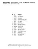
Page 22: ...REPAIR PARTS SNOW THROWER MODEL NO PR8527ES 96192000300 CONTROL PANEL DISCHARGE CHUTE 28 25 20 29 27 7 18 13 14 10 15 14 11 12 22 ...

Page 23: ...at 3 8 Control Assembly Chute Rotater Support Pivot Screw Hex Head 5 16 18 x 3 4 Knob Deflector Bolt Shoulder Washer Flat 1 4 Nut Lock 1 4 20 Bolt Carriage 5 16 18 x 5 8 Washer Nylon Chute Assembly Deflector Assembly Seal Deflector Rivet Blind Knob Speed Control Lever Bolt Carriage 5 16 18 x 3 4 Washer Flat Nut Lock 5 16 18 Lever Assembly Speed Control Retainer Hairpin Rod Upper Speed Control Rod ...

Page 24: ...REPAIR PARTS SNOW THROWER MODEL NO PR8527ES 96192000300 HANDLES 12 7 5 _4 45 9 f 34 42 37 15 47 16 17 22 30 32 31 _J 38 39 40 24 _36 15 19 12 11 48 17 16 24 ...

Page 25: ...l Screw Hex Head 5 16 18 x 1 1 2 Screw Hex Head 5 16 18 x 1 3 4 Handle Assembly LH Includes Grip Handle Assembly RH Includes Grip Nut Lock 5 16 18 Washer Flat 3 8 Knob Handle Rod Auger Control Rod Traction Control End Control Rod Nut Hex Jam 5 16 18 Bolt Carriage 3 8 16 x 2 1 4 Handle Tube Lower Sleeve Spring Spring Traction Drive Spring Auger Control Screw Hex Head 3 8 16 x 1 Bushing Pivot Consol...

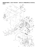
Page 26: ...REPAIR PARTS SNOW THROWER MODEL NO PR8527ES 96192000300 DRIVE 1 3 8 27 18 19 18 43 34 42 7 26 28 26 22 35 33 39 4O ...

Page 27: ...8 x 7 8 22 85179 Retainer Hairpin 23 180135 Spring Bias 24 180081 Gear Axle 58 Teeth 25 178695 Pin Pivot Lever 26 197763 Plate Assembly Drive 27 188226 Shaft Axle 28 197764 Shaft Short Hex 29 175350X479 Lever Shifter Plate 30 175349X479 Bracket Shifter Support 31 72270505 Bolt Carriage 5 16 18 x 5 8 32 189282 Key Square 33 188909 Bearing Flange 34 175338X479 Plate Drive Mounting 35 182504 Spacer B...

Page 28: ...REPAIR PARTS SNOW THROWER MODEL NO PR8527ES 96192000300 CHASSIS ENGINE PULLEYS 30 i3 31 36 34 35 37 29 19 7 6 22 12 11 54 44 45 51 11 46 47 28 57 7 24 15 26 58 27 ...

Page 29: ...cer Engine Pulley 51 Pulley Engine Traction Drive 52 Pulley Engine Impeller Drive 53 Washer Flat 3 8 54 Washer Lock 3 8 55 Screw Hex Head 3 8 24 x 1 3 8 57 58 155452 192213 178830 17490408 179256 187853 180401 195767 73800500 178833X428 187101 192110 178890 700279 179065 179063X428 71210616 175324X428 178624X428 71020512 181156 183852X428 187715X428 193364X008 57079 192275 192147 12000002 11050500...

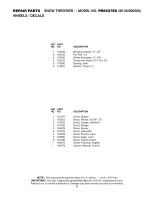
Page 30: ...REPAIR PARTS SNOW THROWER MODEL NO PR8527ES 96192000300 WHEELS DECALS 1 2 4 5 5 4 7 3O ...

Page 31: ...anger 2 193261 Decal Poulan 8 5 HP 27 3 181035 Decal Danger Deflector 4 181042 Decal Danger 5 183879 Decal Poulan 6 181033 Decal Instruction 7 155798 Decal Traction Lever 8 155800 Decal Auger Lever 9 181039 Decal Speed Control 199375 Owner s Manual English 199378 Owner s Manual French NOTE All component dimensions given in U S inches 1 inch 25 4 mm IMPORTANT Use only Original Equipment Manufacture...

Page 32: ...y does not apply to any product which has been sub jected to alteration misuse abuse improper assembly or installation delivery damage or to normal wear of the product 5 Exclusions Excluded from this Warranty are belts shear pins normal wear normal adjustments standard hard ware and normal maintenance 6 In the event you have a claim under this Warranty you must return the product to an authorized ...

Reviews: