If any limit indicators are lit, the heat station components needs to be adjusted to obtain the
required power (see section 6.1. on page 15).
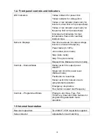
Trip indicators:
These indicators are red in color and are lit if the unit is tripped. No power is
being delivered to the load and the heat OFF indicator will be lit. There are six trip indicators:
•
FREQ: The circuit momentarily operated below the resonant frequency due to a short in the
load or heat station component or poor tuning of the heat station components.
•
CURRENT: The inverter current momentarily exceeded 70A due to a short in the load or
heat station component of poor tuning of the heat station components.
•
DOOR: Indicates that the cover of the unit is not replaced.
•
TEMP: Indicates that the temperature of the heatsink has exceeded 85°C.
•
FLOW: Not used on the 3kW power supply.
•
AUX: An auxiliary interlock wired to the unit has tripped it, or the input AC voltage has
dropped.
4.2. Heat ON/OFF indicators.
These LEDs show whether the power supply is generating output or is off. (identified by
d
in
Figure 2 on page 9).
4.3. Program status indicators.
Identified by
2
in Figure 2 on page 9. These read-outs display the programs status when using
the AUTO mode. The STEP TIME indicator display minutes and the ELAPSED TIME indicator
displays seconds during manual mode operation.
4.4. Voltage, Current and Frequency Indicators.
Identified by
3
in Figure 2 on page 9. These read-outs display the output voltage, the inverter
current and the operating frequency when the power supply is operating.
4.5. Reset Button
Identified by
g
in Figure 2 on page 9. This button is used to clear the fault indicators if a run-
time or interlock trip has occurred. Depressing the button will light the limit and trip indicators
and clear the latch for the fault indicator. If the LED does not go out, then the reason for the
fault is still present.
4.6. Heat switch
Identified by
h
Figure 2 on page 9. When the power supply is energized, and no fault
indicators are lit, putting this switch in the ON (
I
) position will start the power supply delivering
heat. When moved back to the OFF (O) position, the heating will be terminated. While in
AUTO mode, the ON position initiates the heat cycle. Putting the HEAT switch in the OFF
position will terminate the heat cycle.
4.7. Power Pot
Identified by
i
in Figure 2 on page 9. The power pot sets the requested power level as
indicated by the POWER read-out. The level of power feedback is indicated by the percentage
of the LED ring around the POWER POT that is illuminated. This pot is disabled during AUTO
mode operation.
10


