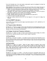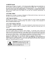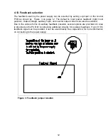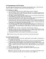
3. Connections
This section gives a description of the required steps to connect the load, input voltage and
what connections to make to run the unit remotely.
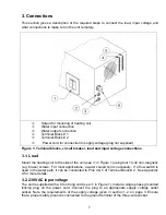
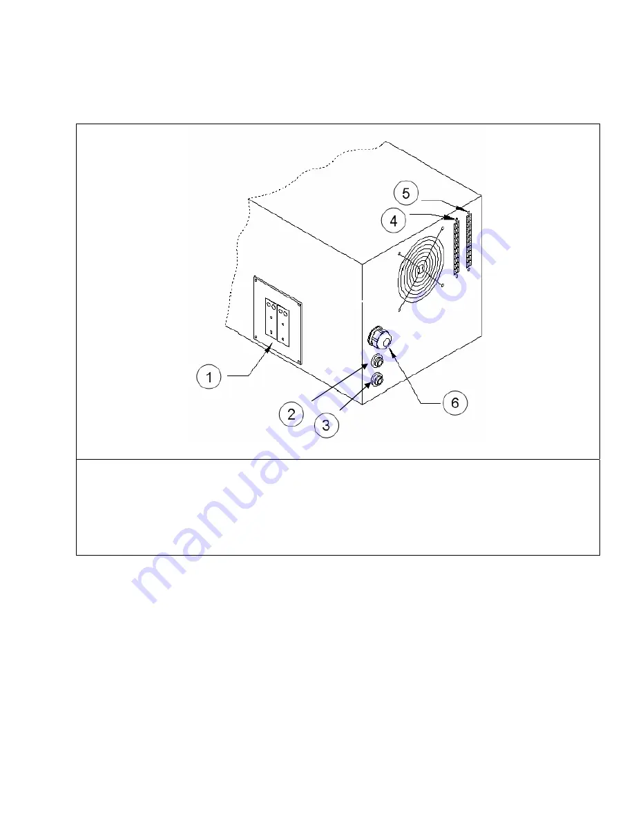
1
Output for mounting of heating coil
2
Water input connection
3
Water output connection
4
Terminal Block # 1
5
Terminal Block # 2
6
Power cord for connection to supply voltage (plug not supplied)
Figure 1: Terminal blocks, circuit breaker, load and input voltage connections.
3.1. Load
Mount the heating coil to the side of the unit (see
1
in Figure 1) using four 10-32 non-magnetic
(e.g. brass) screws. For most applications, a water cooled coil is necessary. If a flow switch is
used in the water path, it can be connected to Pins 4 & 5 of Terminal Block # 2. See Appendix
A for more details.
3.2. 230VAC input voltage
The unit is supplied with a 6 foot long cord (see
2
in Figure 1). Install a single phase grounded
locking plug on the power cord. Connect the plug to an appropriate supply voltage outlet
socket. Note the requirements of the supply voltage given in section 1.2. on page 3. Ensure
that a proper safety ground is connected to the ground terminal of the three-wire socket.
7


