Powered by Safety
®
10
Equipment Description
Power/Vac
®
Metal-Clad Switchgear 5kV & 15kV
01.4IB.67000
e. B
reAker
l
Ift
t
ruck
For ease of breaker handling during installation
and removal, a breaker lift truck is furnished
as a standard accessory with each
Power/Vac switchgear order. This accessory
device is used to elevate the breaker from
the floor or working platform to the level of
the tracks in the switchgear compartment.
Docking of the lifting device rails to the
switchgear tracks is provided for maximum
safety. Refer to
the Removable Element into the Compartment
or the latest version of Instruction Bulletin
01.4IB.66000.
f. r
AtInGS
Ratings of Power/Vac switchgear and circuit
breakers are based on factors supplied in the
following:
• ANSI C37.04 Circuit Breaker Rating
Structure
• ANSI C37.06 Circuit Breaker Ratings
• ANSI C37.20.2 Switchgear Assemblies
See
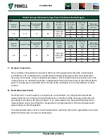
Table B, Ratings of Medium Voltage
Power/Vac® Metal-Clad Switchgear
for complete
ratings.
Note:
Certain non-standard ratings are
available for special applications.
Consult the manufacturer for details.
Refer to the specific job drawings for
detailed voltage ratings applicable to
particular switchgear line-up.
G. l
IGhtInG
I
mpulSe
W
IthStAnd
(BIl)
The basic impulse level is 60kV for the 4.16kV
class switchgear and 95kV for the 8.25kV and
13.8kV class switchgear. The basic impulse
level testing excludes control transformers,
starting reactors, and autotransformers.
Note:
If required, AC Field Dielectric Tests
should be limited to 75% of Factory
Dielectric Test values. Direct current
dielectric testing is not recommended.
If DC testing is required, see
Ch 4 Installation, U. Testing and
for values to be used.
h. c
IrcuIt
B
reAker
r
AckInG
m
echAnISm
The circuit breaker may be placed in three
distinct positions within the circuit breaker
compartment of the switchgear:
• Disconnected Position
• Test Position
• Connected Position
In the “disconnected position” the movable
primary disconnects of the circuit breaker are
disengaged and separated at a safe distance
from the stationary primary disconnecting
devices located in the compartment. A metal
shutter covers the openings of the stationary
primary disconnecting devices which prevents
contact. In this position, the secondary
disconnect devices and control contacts are
disengaged.
In the “test position”, the primary disconnecting
devices are disengaged and the shutters are
closed. The secondary circuits are completed
by inserting the secondary disconnect plug
(breaker) into the secondary disconnect
receptacle of the switchgear compartment via
the breaker mounted handle. Now the circuit
breaker may be electrically operated without
affecting the primary circuit.


