Powered by Safety
®
26
Installation
Power/Vac
®
Metal-Clad Switchgear 5kV & 15kV
01.4IB.67000
2) Outdoor Metal-Clad Switchgear
Switchgear support should be concrete
or reinforced concrete with depth, fill,
drainage, etc., according to recommended
foundation design for the loading, type of
construction, and local conditions involved.
The base furnished with the switchgear
should be supported on a level surface
over the full area of the switchgear. Steel
supporting members should be furnished
if required for leveling the foundation
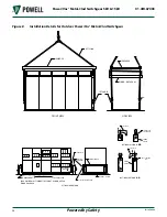
and supporting the switchgear. Refer to
for recommended foundation and
anchoring.
Primary and secondary conduits should be
installed in accordance with the requisition
drawings, before the equipment is put into
place. Conduits must extend no more than
one inch above the finished floor prior to
the installation of the switchgear.
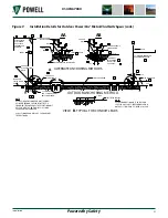
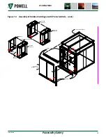
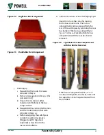
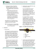
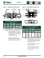
When outdoor pieces of equipment are
shipped in more than one section, the
roof joint between the sections must be
assembled as shown in
. Shipping
sections must be assembled in the proper
sequence due to the location of conduits.
The left hand section of a switchgear lineup
must be positioned in its final location first.
Then the section located immediately to
the right must be positioned as close as the
lifting members permit with the front in
alignment with the first section. Remove
the lifting members and then push or jack
the unit to the left until it is flush with the
first section.
!
CAUTION
Be sure to distribute the forces over the
side frame using appropriate timbers so as
not to deform or damage the surface of the
structure.
3) Outdoor Switchgear with Protected Aisle
a. Remove aisle front wall from the front
of the metal-clad switchgear, discard
all yellow shipping covers on aisle wall
and front of metal-clad switchgear
except lifting members. Reuse 3/8
- 16 hardware. Since the relay and
instrument cases are not weatherproof,
the control panels should be protected
from inclement weather until the
installation of the aisle enclosure is
complete.
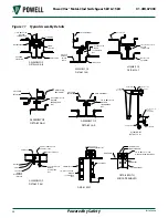
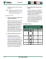
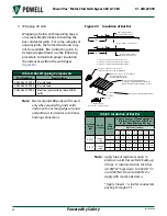
b. Lay down aisle floor in front of each
metal-clad unit
. Secure at
each unit line with tie plate and floor
cap per
. Secure to
metal-clad per
c. For aisle end wall design, disassemble
channel cap, cap bushing, roof cap,
end trim, and corner cap. Reassemble
at end of aisle that has the aisle end
wall. Reuse 1/4 - 20 hardware and plug
buttons.
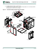
d. Disassemble aisle end extensions
or aisle end extension and aisle end
wall
. Do not
remove shipping support from aisle end
wall.
e. Position aisle end extension(s) and/or
aisle end wall(s) at ends of the line-up.
Secure aisle extension to aisle floor and
metal-clad switchgear
. Secure aisle end wall per
.
f. Set up aisle wall and secure to aisle
floor, aisle end extension(s), aisle end
wall(s) and shipping split.
and
.
g. Apply prestite gasketing material to the
top of aisle wall, metal-clad roof, and
aisle end wall. Punch holes in gasket
with drift pin.


