Powered by Safety
®
27
Installation
01.4IB.67000
h. Remove roof angle (reuse 1/4 - 20
hardware) and set aisle roofs in place,
taking care to align the lap joint
between the aisle and switchgear roof
assemblies before contacting prestite
gasket. Secure roof sections to each
other, to aisle wall and metal-clad
switchgear per
i. Apply RTV clear seal and assemble roof
caps, cap bushings, and channel end
caps.
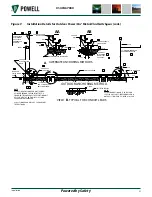
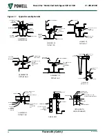
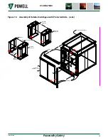
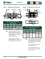
Figure 11, details L & M, P & N
.
j. After steel erection is complete,
check to certify that all bolted, butt,
or overlapped joints are resistant to
water leaks. A source of outside light
in a darkened aisle is an indication that
RTV108 clear seal should be applied to
the exterior surfaces.
k. Assemble grommets in the aisle roof
sections.
l. Assemble and wire the light switches,
receptacles, lamp sockets, etc. in
accordance with the wiring diagrams
furnished with the equipment.
m. Anchor the base of the protected aisle
assembly to the concrete pad using the
anchor clips provided. Install anchor
bolts in accordance with the requisition
drawing.
4) Outdoor Switchgear with Common Aisle
a. Remove and discard the yellow
shipping covers on front of
metal-clad switchgear. Since the
relay and instrument panels are not
weatherproof, the control panel should
be protected from inclement weather
until the installation of the aisle
enclosure is completed.
b. Lay down aisle floor in front of each
metal-clad unit of first switchgear
line-up. Secure to metal-clad per
.
c. Move second switchgear line-up into
position and secure to aisle floor per
. After the switchgear is
secured to the aisle floor, it should be
anchored to the concrete pad using the
anchor clips provided. Install anchor
bolts in accordance with the requisition
drawing.
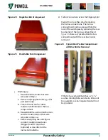
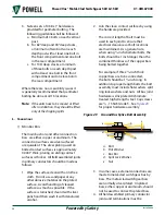
d. For aisle end wall design, disassemble
channel cap, cap bushing, roof cap,
end trim, and corner cap. Reassemble
at end of aisle that has the aisle end
wall. Reuse 1/4 - 20 hardware and plug
buttons.
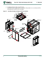
e. Disassemble aisle end extensions
or aisle end
extension and aisle end wall.
. Do not remove
shipping support from aisle end wall.
f. Position aisle end extension(s) and/or
aisle end wall(s) at ends of the lineup.
Secure aisle extension to aisle floor and
metal-clad switchgear
. Secure aisle end wall per
.
g. Apply prestite gasketing material to top
of metal-clad roof and aisle end wall.
Punch holes in gasket with drift pin.
h. Remove roof angle (reuse 1/4 - 20
hardware) and set aisle roofs in place
taking care to align the lap joint
between the aisle and switchgear roof
assemblies before contacting prestite
gasket. Secure roof sections to each
other and to metal-clad switchgear per
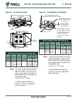
Figure 11, details R, L & M, P & N
.
i. Apply RTV clear seal and assemble roof
caps, cap bushing, and channel end
caps.
j. After steel erection is complete,
check to certify that all bolted, butt
or overlapped joints are resistant to
water leaks. A source of outside light
in a darkened aisle is an indication that
RTV108 clear seal should be applied to
the exterior surfaces.

