Powered by Safety
®
30
Installation
Power/Vac
®
Metal-Clad Switchgear 5kV & 15kV
01.4IB.67000
G. B
reAker
r
emovABle
e
lement
CAUTION
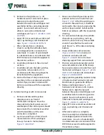
Before inserting a removable element into the
compartment, the racking mechanism must
be in the “TEST/DISCONNECT” position or
damage may occur to the removable element
or the switchgear.
Refer to the instruction bulletin shipped with
the removable element for installation and
operating instructions.
h. t
eSt
c
ABInet
The test cabinet is used to operate a breaker
that has been removed from the metal-clad
switchgear. It should be installed on the wall
at a location where maintenance and testing
of the breaker can be conveniently done.
Conduits must be installed for cables to supply
control power for testing. Make certain that
the green ground conductor is connected to
the electrical ground.
I. A
ddItIon
of
u
nItS
to
e
xIStInG
e
QuIpment
Before adding units to existing equipment,
consult and study all drawings furnished
with the equipment. In addition to the usual
drawings furnished with new equipment,
special drawings may be furnished covering
complicated or special assembly work. Also,
check to make sure all necessary parts are on
hand.
!
CAUTION
Before any covers are removed or any doors
opened which permit access to the primary
circuits, it is essential that the circuit or circuits
be deenergized and breakers be withdrawn to
the test position and tagged.
The information below indicates that special
procedures are required to add new
metal-clad units to outdoor equipment without
a protected aisle and with a protected aisle.
For indoor equipment, it is usually necessary
only to remove the end trim sheets and to
reassemble them on the new units after these
are located and bolted to the existing units.
When the units are in place and bolted
together, assemble the main bus and other
primary connections following the procedure
below.
Secondary wiring and control bus connections
should be made in accordance with the wiring
diagrams furnished with the equipment.
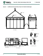
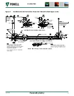
1) Adding Units to Outdoor Equipment without
a Protected Aisle
a. Remove the following items from the
existing metal-clad section and move to
the end of the new addition (except as
noted):
i. Channel End Caps
ii. Roof Caps
iii. Metal-Clad End and Corner Cap
iv. Metal-Clad Front Trim Sheet -
discard
v. Metal-Clad Rear Trim Sheet - discard
vi. Bus Opening Cover - discard
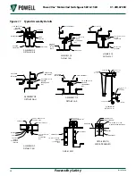
b. To install new metal-clad units:
i. Set new units in place and bolt
together
ii. Assemble bus opening cover, front
and rear trim sheets
iii. Assemble new roof caps and rear
channel end cap
iv. Assemble ground bus splice
between existing and new ground
bus
v. Assemble bus bars and insulating
boots
vi. Reassemble items i-iii from section a.


