Powered by Safety
®
35
Installation
01.4IB.67000
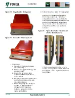
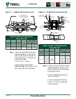
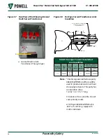
Figure 24 Single Bus Bar Arrangement
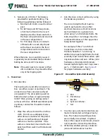
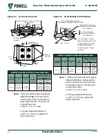
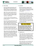
Figure 25 Double Bus Bar Arrangement
j. Finishing up:
i. Reassemble the boots that were
removed in
Step e
.
ii. Remove tape applied in
Step g, i
(for
porcelain only).
iii. Ensure that no tools or other
material is left behind in the bus
compartment.
iv. Reassemble the vertical mid barriers
and the horizontal pan that were
removed in
Steps a-c.
v. Before energizing the switchgear
conduct insulation resistance
(Megger) and HV Hipot test
(optional) as described in the
instruction bulletins.
3) Tie Bus Connections Across the Shipping Split
Steps d thru h
are the same for making
the tie bus connections. The tie bus
compartment can be accessed from the
rear of the switchgear by removing the rear
bus barrier of the tie bus compartment.
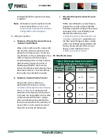
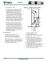
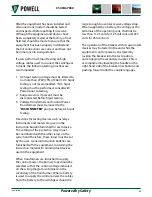
shows a typical bottom tie bus
compartment with the rear bus barrier
removed.
Figure 26 Typical Rear Tie Bus Compartment
with Bus Barrier Removed
If the tie bus compartment has a 2” x 1/4”
aux bus running between stacks, inter-unit
bus supports are not required and will not
be provided.

