Powered by Safety
®
39
Installation
01.4IB.67000
insulated before the operating voltage
is applied.
Note:
All hardware must be tightened to the
torque values listed in
Torque Values for Power/Vac® Medium
.
2) Sliding Connections
a. Stationary Primary Disconnect Devices
- Breakers and Rollouts
Wipe contact surfaces with a clean, soft,
dry, lint-free cloth to remove dirt and
grease from silvered areas. Do not use
any abrasives such as sand paper, emery
cloth or steel wool for this purpose.
Avoid handling of the contact surfaces
after cleaning. Apply a thin coat of
Mobil grease (Red) to the front two
inches of all breaker and rollout primary
disconnect devices. Cover all surfaces,
front, sides, top and bottom evenly.
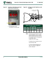
b. Stationary Ground Contact Cluster
Prepare the contact surfaces as
described in the previous section
a. Stationary Primary Disconnect Devices,
giving special
attention to the facing curved surfaces
to be sure no sharp edges or burrs exist
at the narrowest dimension. Apply a
thin coat of Mobil grease (Red) to the
facing curved surfaces for a distance of
no less than 3/4 inch centered around
the point of narrowest dimensions.
c. Movable Primary Disconnect Devices -
Rollouts
Before assembling the contact fingers,
prepare the contact surfaces (double
thickness segment) of the primary tangs
and apply a thin coat of Mobil grease
(Red) as described in section
a. Stationary Primary Disconnect Devices
. Assemble and
pin the contact fingers in place. Apply
a thin coat of Mobil grease (Red) to the
facing curved surfaces of the contact
fingers as described in section
.
m. m
AIn
B
uS
A
SSemBly
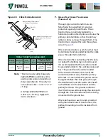
Table C Bolt Torque Values for Power/Vac
®
Medium Voltage Metal-Clad Switchgear
Bolt
Dimensions
(inches)
Bolt
Head
Torque
Ft-Lbs
Kg-M
5/8
55-70
7.6-9.7
1/2
35-50
4.8-6.9
3/8
20-30
2.8-4.2
1/4
5-7
0.7-0.97


