Powered by Safety
®
50
Operation
Power/Vac
®
Metal-Clad Switchgear 5kV & 15kV
01.4IB.67000
Ch 5 Operation
A. G
enerAl
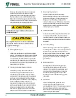
Compartment access shall be permitted ONLY
to “Qualified Person”, as defined in NFPA 70E,
using “approved safe work practice” and
“appropriate PPE”. Failure to do so could
result in death or serious injury.
!
WARNING
All removable elements of the same type and
rating which have duplicate control wiring may
be interchanged.
During operation, all live parts are enclosed by
barriers which permit the operator to perform
work with maximum safety. Separate covers
are provided over each different compartment,
so that any compartment of an enclosure
may be exposed without exposing other
compartments.
All Power/Vac® circuit breakers are equipped
for electrical operation. A manual charging
handle is supplied as part of the accessories to
permit manual operation of the circuit breaker
during maintenance.
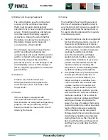
This device must not be used to close the
circuit breaker on any energized circuit. If
done, it could result in death or serious injury.
!
WARNING
The control circuits may be checked accurately
and safely by moving the circuit breaker to
the test position where the main circuits are
disconnected and the control circuits are
completed.
B. I
nSertInG
the
r
emovABle
e
lement
I
nto
the
c
ompArtment
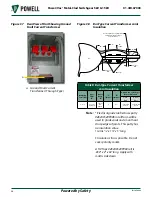
With all primary and control power circuits
deenergized and before installing the
breaker, clean the mating surfaces of the
metal-clad switchgear and circuit breaker
primary disconnects, secondary disconnects,
and ground shoe then apply a thin coating
of 0282A2048P009 contact grease. This will
prevent galling of the silvered contact surfaces.
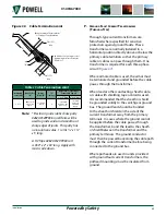
Check the racking mechanism to make certain
that it is in the disconnect position. The tape
indicator should read “Disc/Test” and the
drive nuts on the jack screws should be in the
forward position against their respective stops.
The racking mechanism is accurately leveled
and checked at the factory and should need no
adjustment.
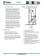
Check the circuit breaker to ensure that it is in
the “OPEN” and “DISCHARGED” position. Attach
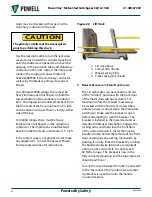
the lift truck to the equipment, after it has been
prepared for docking, by adjusting the height
of the carriage until the docking hooks at the
ends of the arms are slightly higher than the
rail surface in the equipment. When this is
done, position the hooks over the slots in the
rails, and lower them into the slots. Depress
both track roller blocking interlocks
slightly and extend the docking
interlock bars. The interlock bars will pass
under the equipment rails and lock the lift
truck arms to the rails. Do this on both sides.
The track roller blocking interlocks are now
in the raised position and are thus no longer
blocking the track rollers. The lift truck arms
should be approximately level. The breaker can
now be rolled onto or off of the lift truck.
To load the breaker onto the lift truck,
extend each docking interlock bar by slightly
depressing the track roller blocking interlock
and then moving the handle


