Powered by Safety
®
14
Equipment Description
01.4IB.51000C
PowlVac® Metal-Clad Switchgear
5kV & 15kV
l. v
oltAGe
(p
otentIAl
) t
rAnSformer
(r
ollout
c
ArrIAGe
)
The voltage transformers are mounted on a
rollout carriage equipped with primary and
secondary disconnecting devices. When the
voltage transformers are disconnected, they
are at a safe striking distance from all live parts
of the metal-clad switchgear. In addition, a
grounding device is provided which contacts
the fuses when the voltage transformers are
disconnected, effectively discharging the
transformers. In this position, the transformer
fuses may be safely removed and replaced. See
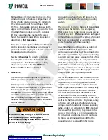
Figure 8. When the voltage transformer rollout
tray is in the disconnected position, the rear
barrier of the tray effectively deters access to
the stationary primary disconnects mounted
in the compartment behind the rollout tray.
However, these stationary primary disconnects
may remain energized.
Do not remove the rollout tray from its rails
without first deenergizing the primary circuit
to which the roll-out connects. Removing the
tray makes the stationary primary disconnect
devices accessible.
!
WARNING
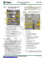
Figure 8
Voltage Transformer and Rollout
Carriage
m. f
uSe
D
ISconnectInG
D
evIce
(r
ollout
c
ArrIAGe
)
Current limiting fuses with high interrupting
rating are sometimes used in metal-clad
switchgear to protect small transformers
or circuits where circuit breakers cannot be
economically or functionally justified.
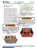
The fuses are mounted on a rollout tray
equipped with disconnecting devices. Control
power transformers of 15kVA and smaller may
be mounted on the rollout with the fuses.
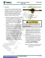
See Figure 9.
Do not remove the rollout tray from its rails
without first deenergizing the primary circuit
to which the roll-out connects. Removing the
tray makes the stationary primary disconnect
devices accessible.
!
WARNING
Figure 9
Control Power Transformer
(Rollout Carriage)


