Powered by Safety
®
17
Installation
01.4IB.51000C
Ch 4 Installation
Contact the Powell Service Division for installation,
maintenance, and renewal parts assistance.
To contact the Powell Service Division, call
1.800.480.7273 or 713.944.6900, or email
It is the responsibility of the purchaser to set
or program components such as protective
relays, meters, timers, etc., in accordance with
the requirements of the particular installation,
before placing the switchgear with vacuum circuit
breakers into service. Programmable devices may
be shipped with temporary programming, used to
test the switchgear. Electromechanical relays may
be shipped in a blocked position to avoid damage
during shipment. Refer to separate instructions for
these components for information on setting or
programming.
A. G
enerAl
This section contains information on receiving,
handling, positioning, power cable termination,
grounding, and checks to make the equipment
ready for operation.
Once the assembly of the metal-clad
switchgear is completed on site, all joints and
hardware, including bus connections, structural
assemblies, and control connections, should
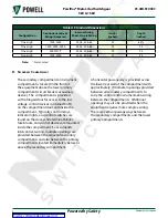
be checked for tightness and proper torque
values. See
for
PowlVac® Metal-Clad Switchgear
.
B. r
eceIvInG
PowlVac switchgear is fabricated in rigid,
floor-mounted, self-supporting steel vertical
sections. Indoor shipping assemblies
are enclosed in a covering to protect the
switchgear lineup from the weather. The
switchgear vertical sections are shipped in an
upright position, and when received should be
kept upright.
When the switchgear lineup reaches its
destination, the purchaser should check the
material actually received against the shipping
list to be sure that all parts have been received.
If damage is found or suspected, file a claim
as soon as possible with the transportation
company and notify the nearest Powell
representative.
The removable elements such as the circuit
breaker will be shipped separately. Refer to
the instruction bulletin furnished for receiving,
storage, and handling instructions on the
circuit breaker.
Some other components, such as top-mounted
resistors or potential transformers, may also
be shipped separately. These components are
identified by a number coinciding with that of
the switchgear vertical section on which they
are to be mounted.
c. h
AnDlInG
It is always preferable to handle a PowlVac
metal-clad switchgear line-up with overhead
cranes, by the lifting means provided on the
switchgear. See Figure 10.
For an outdoor switchgear line-up, lifting
channels are provided and are attached to
the base of the vertical sections. Spreaders
should be used in the slings above the vertical
sections to prevent damage to the top edges
of the switchgear. Do not attempt to lift the
switchgear by using the angles installed on the
sides. The angles are provided only to tie the
vertical sections down during shipment, which
ensures that the unit will not tip over if it is
top-heavy. The angles are not to be used
for lifting purposes. Slings should be tied
to referenced angles to prevent equipment
tipping.


