Powered by Safety
®
50
Operation
01.4IB.51000C
PowlVac® Metal-Clad Switchgear
5kV & 15kV
When transformers are furnished to supply
the control power, the primary taps should be
selected so that the control voltage indicated
on the wiring diagram is obtained on the
secondary of the transformer. When a battery
is used to supply the control power, the cables
from the battery to the switchgear should be
large enough to avoid excessive voltage drop.
When supplied by a battery, the voltage at
the terminals of the operating coils, shall not
be less than the values listed in
Table L, Rated
Control Power Voltages and Ranges for Circuit
Breakers
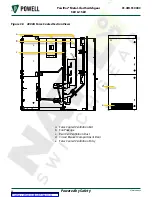
Check continuity between all moving and
stationary contacts of voltage transformer
and fuse rollouts in both the connected and
disconnected (or grounded) positions. The
continuity may be verified with a multimeter or
continuity tester by connecting one test lead
to the bus phase that the stationary device is
connected to and the second lead connected
to the corresponding phase fuse holder cap.
The fuses must be in place for continuity.
CAUTION
Wire connections, accessible bolted bus
connections, and insulated joints should be
examined to make sure they have not been
loosened or damaged during shipment or
installation.
After the switchgear has been installed and all
connections to the apparatus it is to control
have been made, it should be given a final
check and test before being energized.
The connections to the equipment apart
from the switchgear, such as instrument
transformers, remote control and interlock
circuits, and auxiliary switches should be
checked for continuity and phase relationship.
The covers for meters, relays, and other devices
which have to be removed during the course
of installation and test should be carefully
handled when removed. The covers should be
put back in place promptly to keep dust and
dirt from collecting on the vital relay parts.
Do not attempt to energize the equipment
until all connections are verified. Improper
connections could result in death or serious
injury.
!
WARNING
After the switchgear has been installed and put
into operation, the drawings supplied with the
equipment should be reviewed and notations
made on them of any changes made during
the installation.
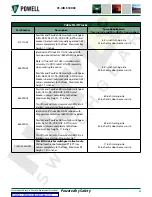
Table L Rated Control Power Voltages & Ranges
for Circuit Breakers
Nominal Control
Power Voltage
Voltage Range
Required at
Tripping Coil
Terminals
Voltage Range
Required (dc)
at Closing Coil
Terminals
24VDC
14 to 28 VDC
---
48VDC
28 to 56 VDC
38 to 56 VDC
125VDC
70 to 140 VDC
100 to 140 VDC
250VDC
140 to 280 VDC
200 to 280 VDC
120VAC
104 to 127 VAC
104 to 127 VAC
240VAC
208 to 254 VAC
208 to 254 VAC


