User Guide Gamatronic Electronic Industries Ltd.
µ
PS-SP 3:3, 3x220 in, 3x208 60 Hz out
Communications
36
6.3
Remote Monitor Box (Optional)
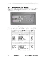
The remote monitor box can be located a maximum distance of 50m from the UPS. It
is directly connected to the UPS with a 4-wire cable connected to the REMOTE
MONITOR interface of the UPS.
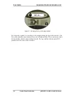
Figure 15: Remote Monitor Box
The monitor panel on the front of the monitor box displays audio and visual
information about the condition of the UPS, the mains, and the load. Its LEDs are
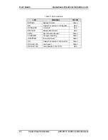
color coded. The meaning of each of the LEDs is explained in the following table:
LED
MEANING
COLOR
BYPASS Bypass
Normal
Green
BYPASS
Fault in Bypass
Red
B/P
Output Connected to the Bypass
Red
OVERLOAD
Overload (Load more than 100%)
Red
BATTERY
Battery Faulty
Red
BATTERY
Battery Normal
Green
CHARGER
Input voltage is OK
Green
CHARGER
Input voltage is not OK
Red
INVERTER
Inverter is OK
Green
INVERTER
Inverter is faulty
Red
INV
Output Connected to the Inverter
Green
LOAD LEVEL
Load Level
Green
LOAD LEVEL
Load Greater Than 100%
Red
UPS ON
UPS is activated
Green
ALARM OFF
Fault in the system
Red
SYNC
Bypass voltage is synchronized
with
Table 4: LED Indicators on Remote Monitor Panel
Summary of Contents for PS-SP Series
Page 1: ......

